
Anti-floating pile structure for soft soil foundation and construction method of anti-floating pile structure during wet season

A technology of soft soil foundation and construction method, which is applied in the direction of foundation structure engineering, sheet pile wall, protection device, etc., can solve problems such as damage effects, and achieve the effect of improving strength, guaranteeing structural strength, and ensuring the effect of bottom expansion.

Pending Publication Date: 2019-09-10
CITIC GUOAN CONSTR GRP CO LTD
View PDF0 Cites 2 Cited by
  • Summary
  • Abstract
  • Description
  • Claims
  • Application Information

AI Technical Summary

Problems solved by technology

[0005] The purpose of the present invention is to provide an anti-floating pile structure used in soft soil foundations and its construction method in wet seasons, to solve the problem in the prior art that the bottom of the bottom-expanded anti-floating pile is affected by shear damage, and to achieve a reduction in expansion. The bottom anti-floating pile is damaged by shear stress, and the purpose of improving the strength of the anti-floating pile

Method used


Image

  • Anti-floating pile structure for soft soil foundation and construction method of anti-floating pile structure during wet season
  • Anti-floating pile structure for soft soil foundation and construction method of anti-floating pile structure during wet season
  • Anti-floating pile structure for soft soil foundation and construction method of anti-floating pile structure during wet season

Examples


Embodiment 1

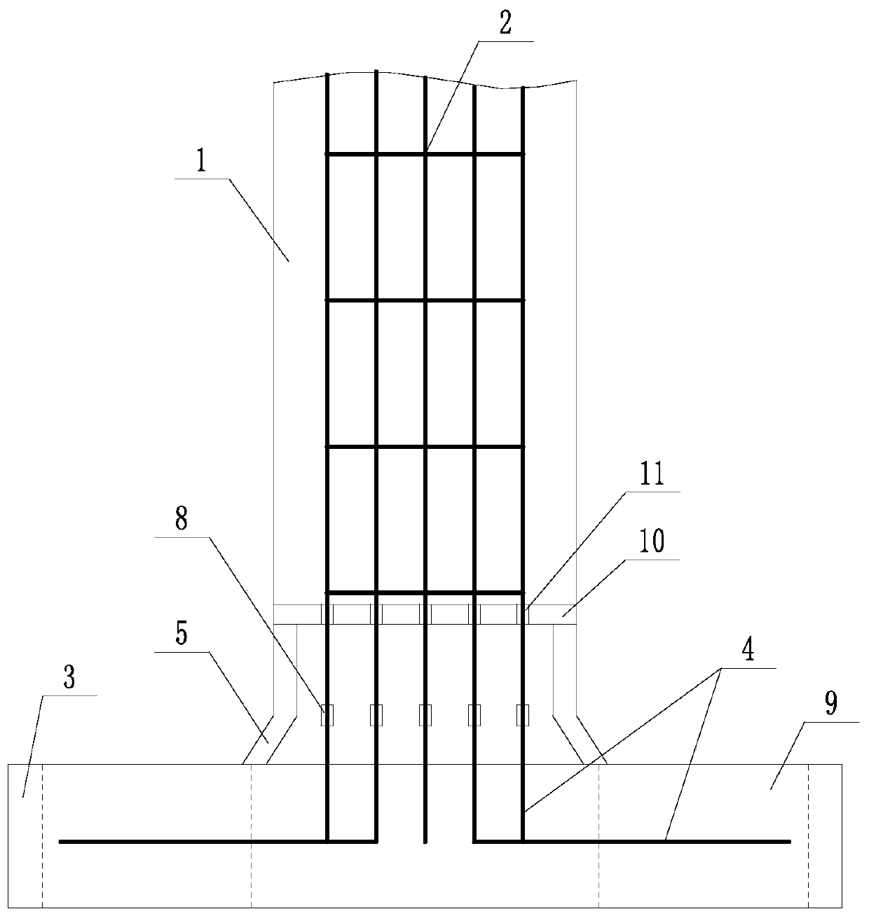
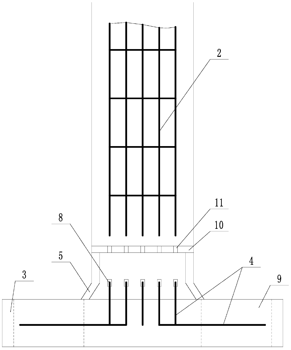
[0038] like Figure 2 to Figure 5 The shown anti-floating pile structure used in soft soil foundations includes a pile body 1 and a reinforcement cage 2 located inside the pile body 1. It is characterized in that it also includes a cap 3, and the upper surface of the cap 3 is provided with an annular The sleeve 5 and the cap 3 are provided with a number of preset ribs 4, the preset ribs 4 protrude from the upper surface of the cap 3 inside the sleeve 5, and the protruding preset ribs 4 are connected with the main ribs at the bottom of the reinforcement cage 2 One by one is facing; the top of the preset rib 4 is provided with a socket 6, and the bottom end of the main reinforcement on the steel cage 2 is provided with an insertion part 7 that matches the socket 6, and each insertion part 7 is inserted into the corresponding In the socket 6; the connection between the insertion part 7 and the socket 6 is also provided with a protective cover 8; a number of through holes 9 are pr...

Embodiment 2

[0044] like Figure 2 to Figure 5 In the shown anti-floating pile structure used in soft ground, on the basis of Example 1, the cap 3 and the sleeve 5 are all prefabricated concrete structures. It also includes a limiting plate 10 fixed on the top of the sleeve 5, a number of circularly distributed perforations 11 are arranged on the limiting plate 10, and several perforations 11 are directly opposite to the main reinforcements at the bottom of the reinforcement cage 2, and the main reinforcements at the bottom of the reinforcement cage 2 are respectively from Several perforations 11 pass through. The perforations 11 are directly opposite to the protective sleeves 8 one by one. The protective cover 8 includes a diameter-expanding part 801 distributed up and down, and a mounting part 802. The mounting part 802 is screwed to the top of the pre-set rib 4. The inner diameter of the diameter-expanding part 801 is larger than the outer diameter of the main reinforcement on the rein...

Embodiment 3

[0046] As the construction method of the anti-floating pile structure in the high water period in any of the above-mentioned embodiments, it may further comprise the steps:

[0047] (a) Excavate the foundation pit, the size of the foundation pit must be able to accommodate the cap 3;

[0048] (b) lift cap 3 and place it at the bottom of the foundation pit;

[0049] (c) lifting the reinforcement cage 2 vertically, so that the insertion part 7 on the main reinforcement at the bottom end of the reinforcement cage 2 is all inserted into the socket 6 at the top of the corresponding preset reinforcement 4;

[0050] (d) Formwork is set outside the reinforcement cage 2, and the foundation pit on the outside of the formwork is backfilled;

[0051] (e) Pour concrete into the formwork, take out the formwork after the pouring is completed, and wait for Ning.

[0052] A more preferred embodiment is that it also includes a limiting plate 10 fixed on the top of the sleeve 5 , so that each ...


PUM


Abstract

The invention discloses an anti-floating pile structure for a soft soil foundation and a construction method of the anti-floating pile structure during the wet season. The anti-floating pile structurecomprises a pile body, a reinforcement cage located in the pile body and a bearing platform, wherein an annular sleeve is arranged on the upper surface of the bearing platform, a plurality of pre-arranged ribs are arranged in the bearing platform, the pre-arranged ribs extend out of the upper surface of the portion, located inside the sleeve, of the bearing platform, and the extending pre-arranged ribs are in one-to-one correspondence with main ribs at the bottom end of the reinforcement cage; inserting openings are formed in the top ends of the pre-arranged ribs, inserting parts matched withthe inserting openings are arranged at the bottom ends of the main ribs on the reinforcement cage, and each inserting part is inserted into the corresponding inserting opening; a protective sleeve isfurther arranged at the joint of each inserting part and the corresponding inserting opening; a plurality of through holes are formed in the bearing platform, and the through holes and the pre-arranged ribs do not interfere with each other. The anti-floating pile structure for the soft soil foundation and the construction method of the anti-floating pile structure during the wet season can solvethe problem that the bottom of a bottom-expanded anti-floating pile is affected by shear damage in the prior art, and the purposes of lowering the damage of shear stress on the bottom-expanded anti-floating pile and improving the strength of the anti-floating pile are achieved.

Description

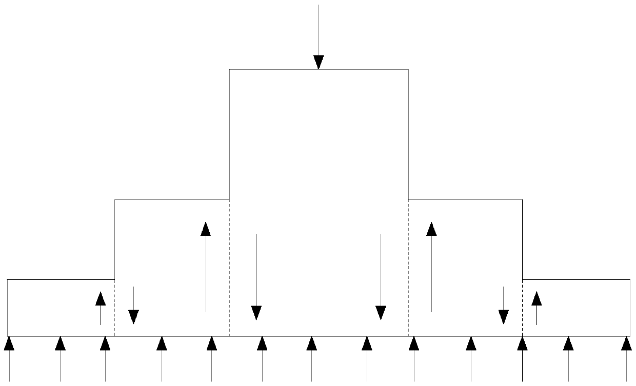
technical field [0001] The invention relates to the field of anti-floating piles, in particular to an anti-floating pile structure used in soft soil foundations and a construction method thereof in a wet season. Background technique [0002] Anti-floating piles are different from ordinary foundation piles, and have their own unique properties. The biggest difference from ordinary foundation piles is that foundation piles are usually compression piles, and the pile body bears the building load pressure, and the force is transmitted from the top of the pile to the bottom of the pile. , the force on the pile body changes with the change of the building load; while the anti-floating pile is an anti-floating pile, the pile body bears tension, and the force on the ordinary anti-floating pile is also transmitted from the top of the pile to the bottom of the pile, and the force on the pile body It changes with the change of groundwater level, but the force mechanism of the two is ju...

Claims


Application Information

Patent Timeline
IPC IPC(8): E02D31/12E02D5/38E02D5/44
CPCE02D31/12E02D5/38E02D5/44E02D5/385
Inventor 程晓波徐新华唐伟明范丹平唐徐东张海涛
Owner CITIC GUOAN CONSTR GRP CO LTD
Learn More