
Smart home remote anti-theft monitoring system and method

A smart home and remote technology, applied in the field of transportation, can solve the problems of no monitoring and judgment logic, inability to intelligently identify passers-by and visitors outside the door, and fish that slip through the net.

Active Publication Date: 2021-03-02
CHONGQING UNIV
View PDF11 Cites 0 Cited by
  • Summary
  • Abstract
  • Description
  • Claims
  • Application Information

AI Technical Summary

Problems solved by technology

In terms of comprehensive functions, most common anti-theft monitoring systems have defects and deficiencies. They cannot intelligently identify passers-by and coming people outside the door, which may easily cause misjudgment; they cannot make different reactions according to the level of intelligent judgment, such as: prompting users, Automatic alarm; there is no mobile phone APP connected to the Internet cloud at the same time to monitor the situation in front of the user's door and remotely control the hardware system in front of the door, so as to achieve the purpose of counteracting illegal behavior anytime and anywhere
[0003] In terms of safety factors, the monitoring and judgment of ordinary anti-theft monitoring systems is extremely simple. Generally, the target is simply judged only through infrared monitoring and camera video image analysis; there is no separate and progressive monitoring judgment logic, and it is impossible to distinguish passers-by from suspects , It is easy to cause fish that slip through the net; it is impossible to make different reactions according to different judgment results, so as to inform users in time to use mobile APP and other channels for real-time remote monitoring; there are also defects in automatic alarms
[0004] In terms of energy saving, ordinary anti-theft monitoring systems usually use a network camera that is turned on for 24 hours to monitor, which consumes a lot of power and traffic, and the monitoring judgment is not accurate enough

Method used


Image

  • Smart home remote anti-theft monitoring system and method
  • Smart home remote anti-theft monitoring system and method
  • Smart home remote anti-theft monitoring system and method

Examples


Embodiment Construction

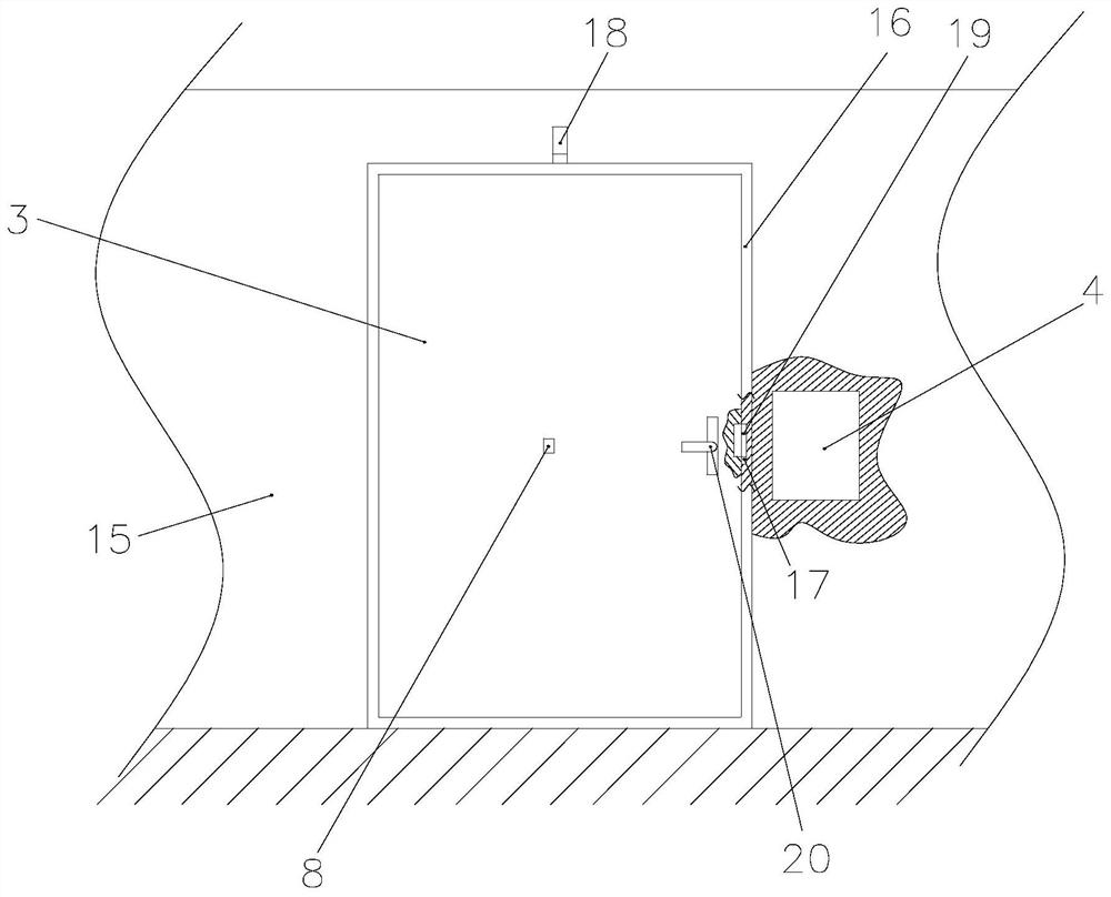
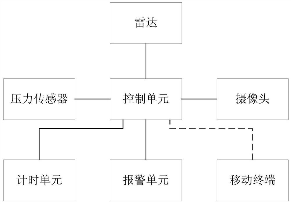
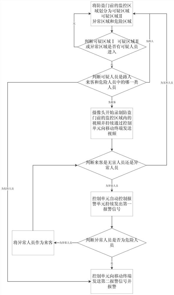
[0066] Such as figure 1 with figure 2 As shown, a smart home remote anti-theft monitoring system provided by the present invention includes: a control unit, a radar, a camera, a pressure sensor and an alarm unit; Appearing suspicious personnel, and send suspicious personnel position signals to the control unit; the outside of the security door refers to the side of the security door facing the outside of the house, and the middle part of the outside of the security door refers to the height of the outside wall of the security door being the height of the security door. And the width is the width of the anti-theft door location. In this embodiment, the radar monitors the distance between the suspicious person appearing in the monitoring area in front of the anti-theft door and the radar belongs to the existing function of the radar, that is, the prior art, and will not be repeated here. It should be noted that the technical solution for the radar to obtain the distance be...


PUM


Abstract

A smart home remote anti-theft monitoring system provided by the present invention includes: a control unit, a radar, a camera, a pressure sensor, and an alarm unit; Send the suspicious person position signal to the control unit; the pressure sensor is arranged on the anti-theft door frame close to the lock cylinder, and the force sensing surface of the pressure sensor faces the anti-theft door, which is used to sense the pressure signal applied by the anti-theft door to the anti-theft threshold and send the pressure The signal is sent to the control unit; the invention can accurately identify the behavior of suspicious persons in the monitoring area in front of the anti-theft door, precisely control the opening and closing of the monitoring camera, realize remote anti-theft monitoring, and realize automatic and manual alarm control at the same time, reducing the need for At the same time, the misjudgment of suspicious personnel's behavior improves the accuracy and safety factor of anti-theft monitoring, reduces energy consumption, and makes resource utilization more reasonable.

Description

technical field [0001] The invention relates to the field of traffic, in particular to a remote anti-theft monitoring system and method for smart home. Background technique [0002] With the development of the Internet of Things, smart homes have entered people's lives step by step, and the most important thing to pay attention to is security. Most of these monitoring systems currently on the market only have simple and basic anti-theft functions, such as monitoring and feedback of video information. In terms of comprehensive functions, most common anti-theft monitoring systems have defects and deficiencies. They cannot intelligently identify passers-by and coming people outside the door, which may easily cause misjudgment; they cannot make different reactions according to the level of intelligent judgment, such as: prompting users, Automatic alarm; there is no mobile phone APP connected to the Internet cloud at the same time to monitor the situation in front of the user's ...

Claims


Application Information

Patent Timeline
Patent Type & Authority Patents(China)
IPC IPC(8): G08B13/08G08B13/181H04N5/232H04N5/76H04N7/18
CPCG08B13/08G08B13/181H04N7/18H04N5/76H04N23/651
Inventor 江佩轩宋祥铭何雯雯刘富樯
Owner CHONGQING UNIV
Learn More