
3D printing fracture fixing device

A fixation device and 3D printing technology, applied in fractures, medical science, etc., can solve problems such as inability to fit plaster tightly, cumbersome removal process, and affect bone healing, so as to improve the fixation effect, facilitate use, use and storage Effect

Inactive Publication Date: 2019-09-06
南宁壶兰科技有限公司
View PDF17 Cites 0 Cited by
  • Summary
  • Abstract
  • Description
  • Claims
  • Application Information

AI Technical Summary

Problems solved by technology

[0003] Fracture is a relatively serious trauma. After the fracture occurs, the muscles attached to the bone will contract spasmodically, so it is very painful. Because the healing of the fracture takes a long time, it is necessary to use external fixation to maintain the correct position of the fracture after reduction. To prevent it from shifting again, the commonly used external fixation method is to use plaster to fix the patient's fracture. The process of plaster fixation and removal is too cumbersome, and the air permeability is poor. During the fracture healing process, there will be swelling. Detumescence will cause a certain gap between the plaster and the fracture. However, after the plaster is finalized, the binding strength between it and the limb cannot be adjusted, resulting in the inability of the limb to fit closely with the plaster in the later stage, which affects the healing of the bone in the later stage.

Method used


Image

  • 3D printing fracture fixing device
  • 3D printing fracture fixing device
  • 3D printing fracture fixing device

Examples


Embodiment Construction

[0028] In order to make the object, technical solution and advantages of the present invention clearer, the present invention will be further described in detail below in combination with specific embodiments and with reference to the accompanying drawings. It should be understood that these descriptions are exemplary only, and are not intended to limit the scope of the present invention. Also, in the following description, descriptions of well-known structures and techniques are omitted to avoid unnecessarily obscuring the concept of the present invention.

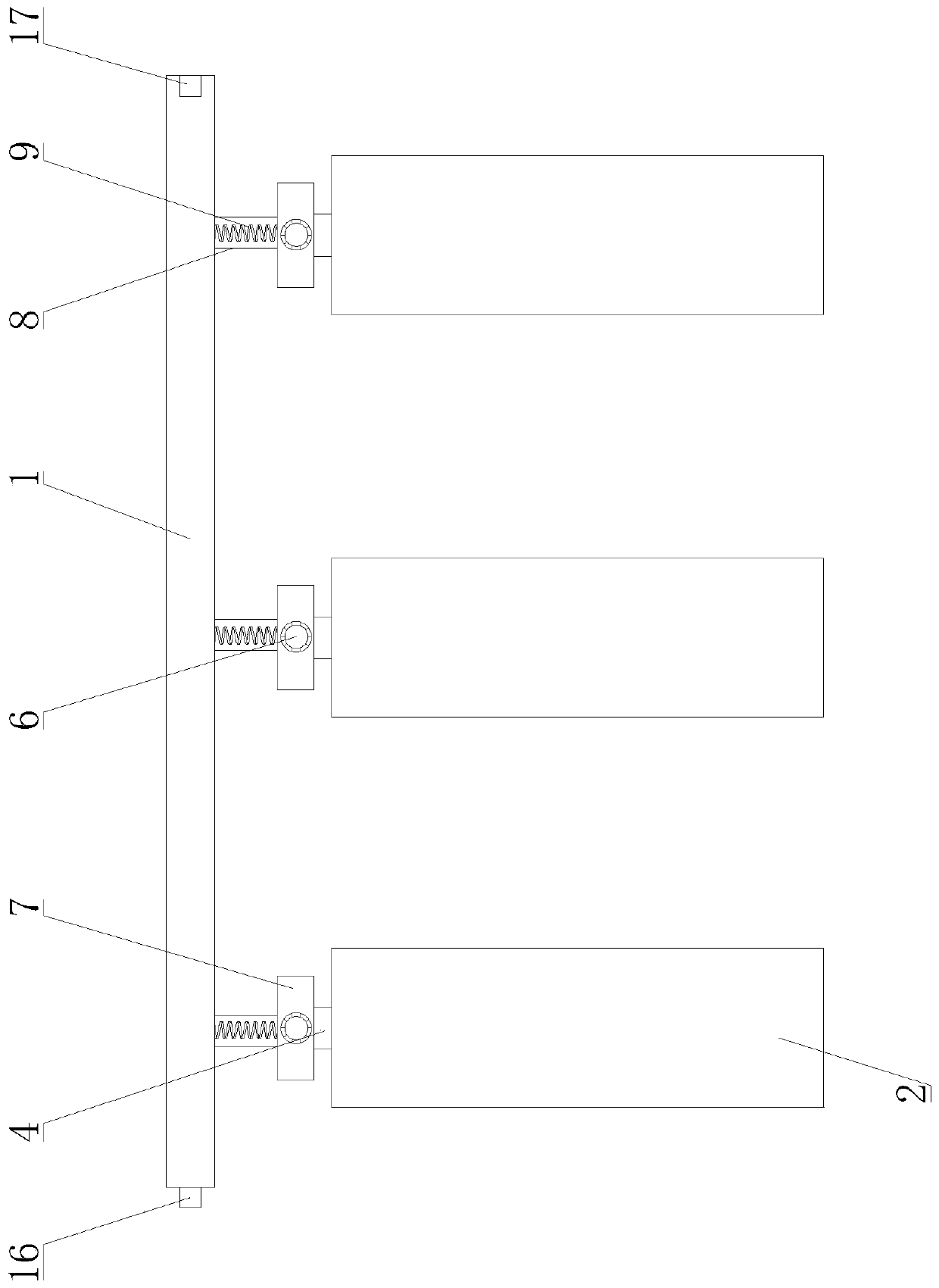
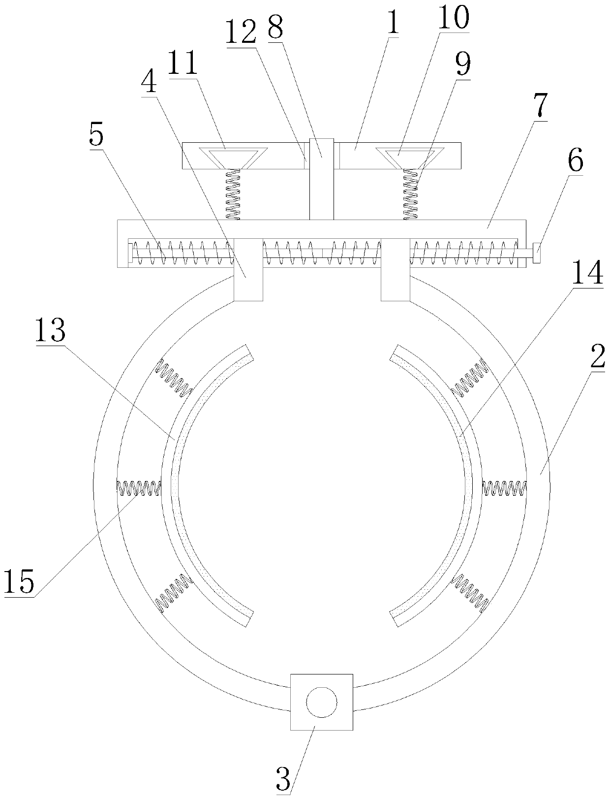
[0029] Such as Figure 1-3 As shown, a 3D printing fracture fixation device proposed by the present invention includes a connecting piece 1, a fixing plate 2, a first fixing piece 3, a moving piece 4, a two-way threaded rod 5, a rotary knob 6, a second fixing piece 7, Locking part 8, first elastic part 9, splint 13 and second elastic part 15;

[0030] The second fixing part 7 is positioned at the below of the connecting...


PUM


Abstract

The invention discloses a 3D printing fracture fixing device. The fixing device a connecting piece, fixing plates, a first fixing member, moving members, a two-way threaded rod, a turn knob, a secondfixing member, a locking member, first elastic members, clamping plates and second elastic members; the locking member is vertically arranged on the second fixing member and inserted into the connecting piece; the first elastic members are vertically arranged on the second fixing member and connected to sliding members; the sliding members are slidingly connected to the connecting piece; the two-way threaded rod is horizontally arranged on the second fixing member; the two moving members are located on the two ends of the two-way threaded rod and respectively in threaded connection with the two-way threaded rod; the turn knob is connected to the two-way threaded rod; the fixing plates are rotatably arranged on the two sides of the first fixing member and connected to the moving members; the clamping plates are located on the inner sides of the fixing plates; and the second elastic members are connected to the clamping plates and the fixing plates. The fixing device can adjust the positions of the fixing plates and the opening ranges of the clamping plates, so that the fixing device is suitable for different patients and different parts, and is good in fixing effect, simple in operation, convenient in installation and dismounting and convenient for usage and storage.

Description

technical field [0001] The invention relates to the technical field of fracture fixation devices, in particular to a 3D printed fracture fixation device. Background technique [0002] 3D printing is a kind of rapid prototyping technology. It is a technology based on digital model files and using bondable materials such as powdered metal or plastic to construct objects by layer-by-layer printing. 3D printing usually uses It is realized by digital technology material printers, often in the fields of mold manufacturing, industrial design, etc., and is usually used to manufacture models, and then gradually used for direct manufacturing of some products. There are already parts printed using this technology. This technology Applications in Jewelry, Footwear, Industrial Design, Architecture, Engineering and Construction (AEC), Automotive, Aerospace, Dentistry, Medical Industry, Education, Geographic Information Systems, Civil Engineering, Firearms, and more 3D printing technology...

Claims


Application Information

Patent Timeline
IPC IPC(8): A61F5/058
CPCA61F5/058
Inventor 韦仁钟义广韩星温宗华梁周
Owner 南宁壶兰科技有限公司
Learn More