
A control panel terminal

A terminal block and control board technology, which is applied in the direction of connection, fixed connection, conductive connection, etc., can solve the problems of wire ends being exploded, and the wire is not easy to connect to the terminal, so as to improve the sealing performance, avoid poor contact, and improve work efficiency. Effect

Active Publication Date: 2020-12-15
安徽赛时达显示科技有限公司
View PDF11 Cites 0 Cited by
  • Summary
  • Abstract
  • Description
  • Claims
  • Application Information

AI Technical Summary

Problems solved by technology

[0004] Although this type of technical solution is used, the design is compact, safe and reliable, and it is more convenient for the automatic assembly of industrial manipulators; Modify the compiled code. At this time, the sensors, relays, and power supplies connected to the control board need to be replaced according to the working conditions. Therefore, frequent wiring needs to be performed on the terminals on the control board. After the wires are connected to the terminals, the wires will be blocked. The terminal is compressed and deformed, and the wire end will explode. At this time, when wiring into the terminal, the wire is not easy to connect into the terminal. Therefore, we propose a control board terminal to solve the above problems

Method used


Image

  • A control panel terminal
  • A control panel terminal
  • A control panel terminal

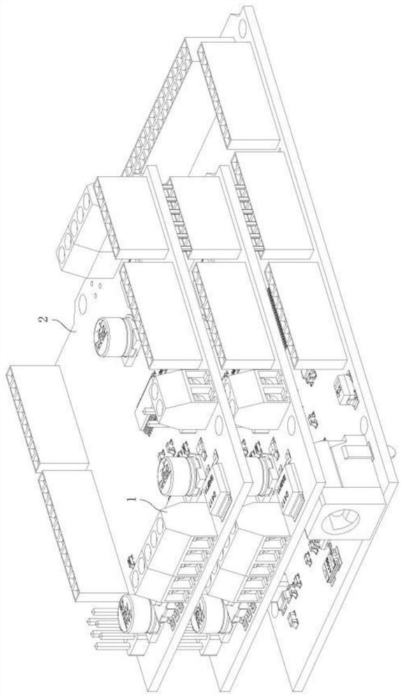
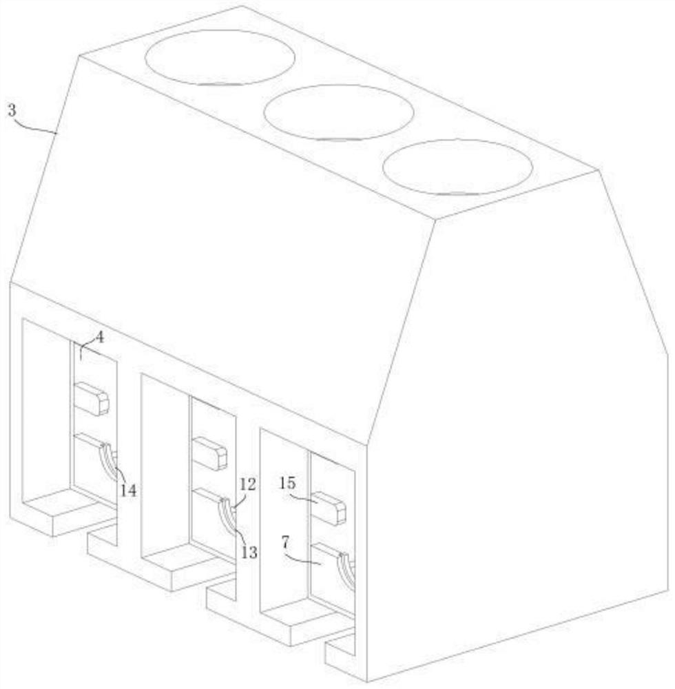
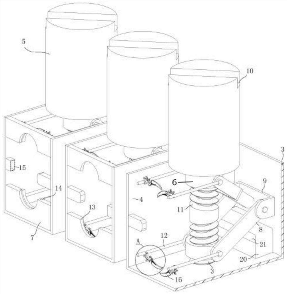
Examples


Embodiment Construction

[0023] In order to make the technical means, creative features, goals and effects achieved by the present invention easy to understand, the following will further elaborate the present invention in conjunction with the specific embodiments. image 3 as the benchmark.

[0024] Such as Figure 1 to Figure 4 As shown, a control board connection terminal according to the present invention includes a terminal 1, the terminal 1 is located on the control board 2, the terminal 1 is fixedly connected to the control board 2, and the terminal 1 includes a housing 3, a wire chamber 4, Stud 5, slide block 6, clamping plate 7, support plate 8 and support 9, described line room 4 is located in casing 3, line room 4 is fixedly connected with case 3, and line room 4 is provided with Stud 5; the stud 5 is rotatably connected in the wire chamber 4 and the housing 3, the upper end of the stud 5 is provided with a slot 10, and the lower end of the stud 5 is provided with two sections of screw 11;...


PUM


Abstract

The invention belongs to the technical field of low-voltage electric appliances and in particular to a control board binding post comprising a terminal, wherein the terminal is located on a control board and is fixedly connected with the control board; the terminal comprises a housing, a line housing room, a stud, slide blocks, an engagement board, a support plate and a support base; the line housing room is located in the housing and is fixedly connected to the housing; the stud is arranged in the line housing room and is rotatably connected in the line housing room and the housing; the upperend of the stud is provided with a straight slot; the lower end of the stud is provided with two lead screws having different screwing directions and provided with the slide blocks; the two slide blocks and the two lead screws form lead screw nut pairs; the slide blocks are fixedly connected with the engagement board through support shafts; the slide blocks are rotatably connected with the support plate; and the support plate is rotatably connected in the support base. When the support plate rotates, a wire end is compressed so that the dispersed wire end is pressed toward the middle part soas to pass more currents in the wire and avoid poor contact of the wire in the terminal. The engagement board and the stud that allow the wire with a dispersed wire end to be easily inserted into theterminal.

Description

technical field [0001] The invention belongs to the technical field of low-voltage electrical appliances, in particular to a control board terminal. Background technique [0002] Terminal blocks are widely used in modular instruments, including isolated safety barriers, isolators, temperature transmitters, power transmitters, etc. With the improvement, the demand for terminal blocks in the field of electronic and electrical connections is also increasing. There are many types of terminal blocks, most of which are composed of insulating plastics, metal sheets and related fixtures. [0003] There are also some terminal technical solutions in the prior art. For example, a Chinese patent with application number 2013103988598 discloses a terminal; a terminal used in the field of electrical connection, including a terminal housing, a terminal pin, a concave Slotted plugs, slot holes are reserved on the terminal shell in the design, which can realize the automatic assembly of the ...

Claims


Application Information

Patent Timeline
Patent Type & Authority Patents(China)
IPC IPC(8): H01R9/24H01R4/42H01R12/51
CPCH01R4/42H01R9/24H01R12/515
Inventor 臧龙兰凤王海龙
Owner 安徽赛时达显示科技有限公司
Learn More