


Quick Research
Generate reliable direction feasibility study reports for your R&D in just a few steps.

Technical Q&A
Discover and master advanced knowledge NOW. Basics, ideas, possibilities, all at once.

Find Solutions
As an expert in R&D theories, this can generate solutions to your technical problems instantly.

Evaluate Feasibility
Analyze your overall solution with one click, know your potential R&D risks in advance.

Monitor Landscape
Get weekly tech updates, stay abreast of the latest tech innovations and key insights.
Pendulum contrast demonstration circuit and instrument
A circuit and relay technology, applied in the field of pendulum comparison demonstration circuits and instruments, can solve the problems of large error and low efficiency, and achieve the effect of accurate automatic counting, accurate experimental conclusions and time saving.
- Summary
- Abstract
- Description
- Claims
- Application Information
AI Technical Summary
Problems solved by technology
Method used
Image


Examples
Embodiment 1
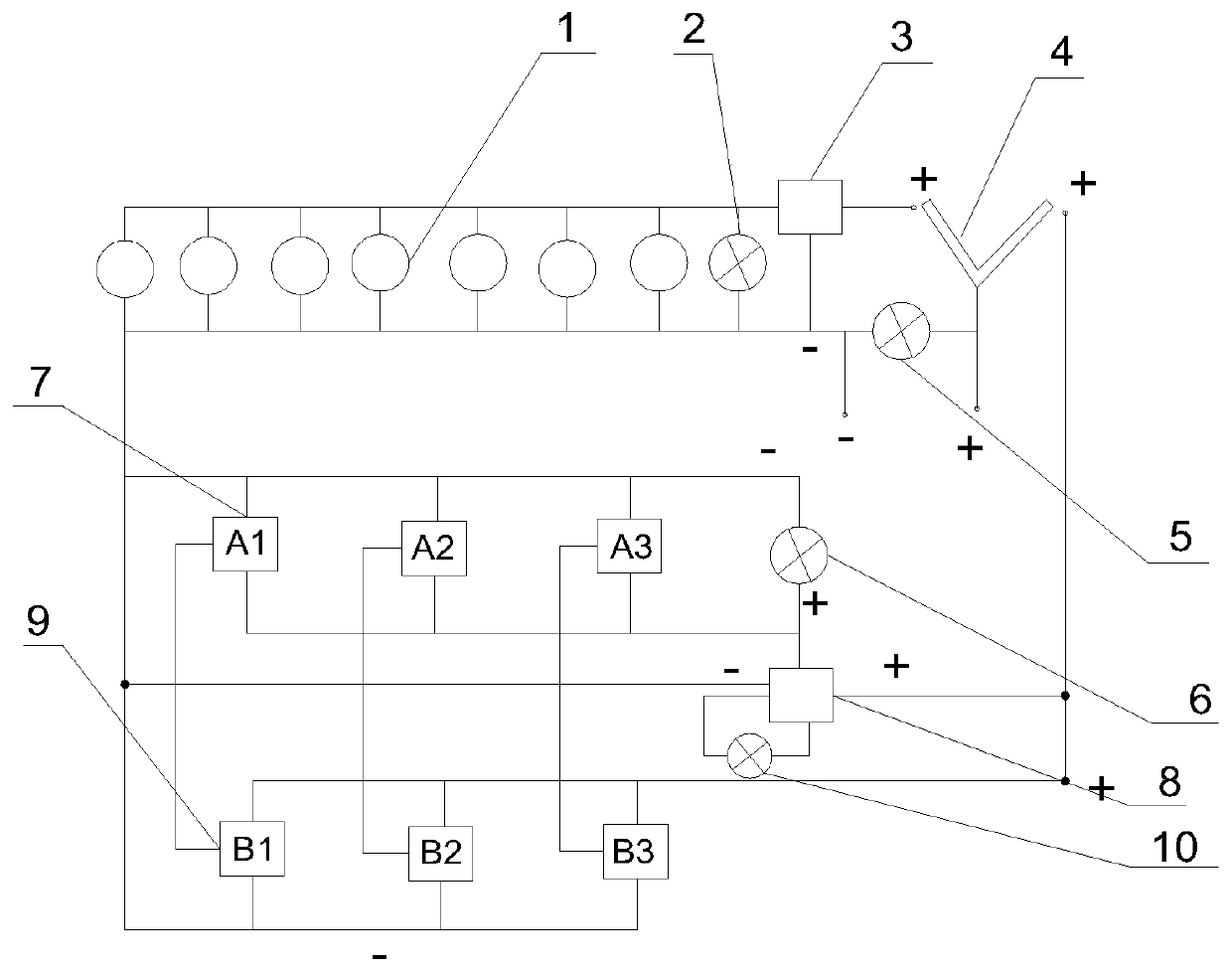
[0026] Such as figure 1 with image 3 As shown, the pendulum comparison demonstration circuit includes a plurality of photoelectric switches 7 (A1, A2, A3), a plurality of counters 9 (B1, B2, B3), a second timing relay 8, a plurality of magnetic coils 1, a first timing Relay 3, start switch 4, magnetic coil lamp 2, power supply lamp 5, work indicator light 6 and stop counting indicator light 10, magnetic coil 1 is seven, and the positive ends of the power supply of multiple magnetic coil 1 are respectively connected to the first The positive power output terminal of a timing relay 3 and the negative power terminals of a plurality of magnetic coils 1 are respectively connected to the negative power output terminal of the first timing relay 3, and the positive power terminal of the first timing relay 3 is used to connect with the start switch 4 , for connection to the positive terminal of the power supply. The first timing relay can also be replaced by a temperature controller...
Embodiment 2
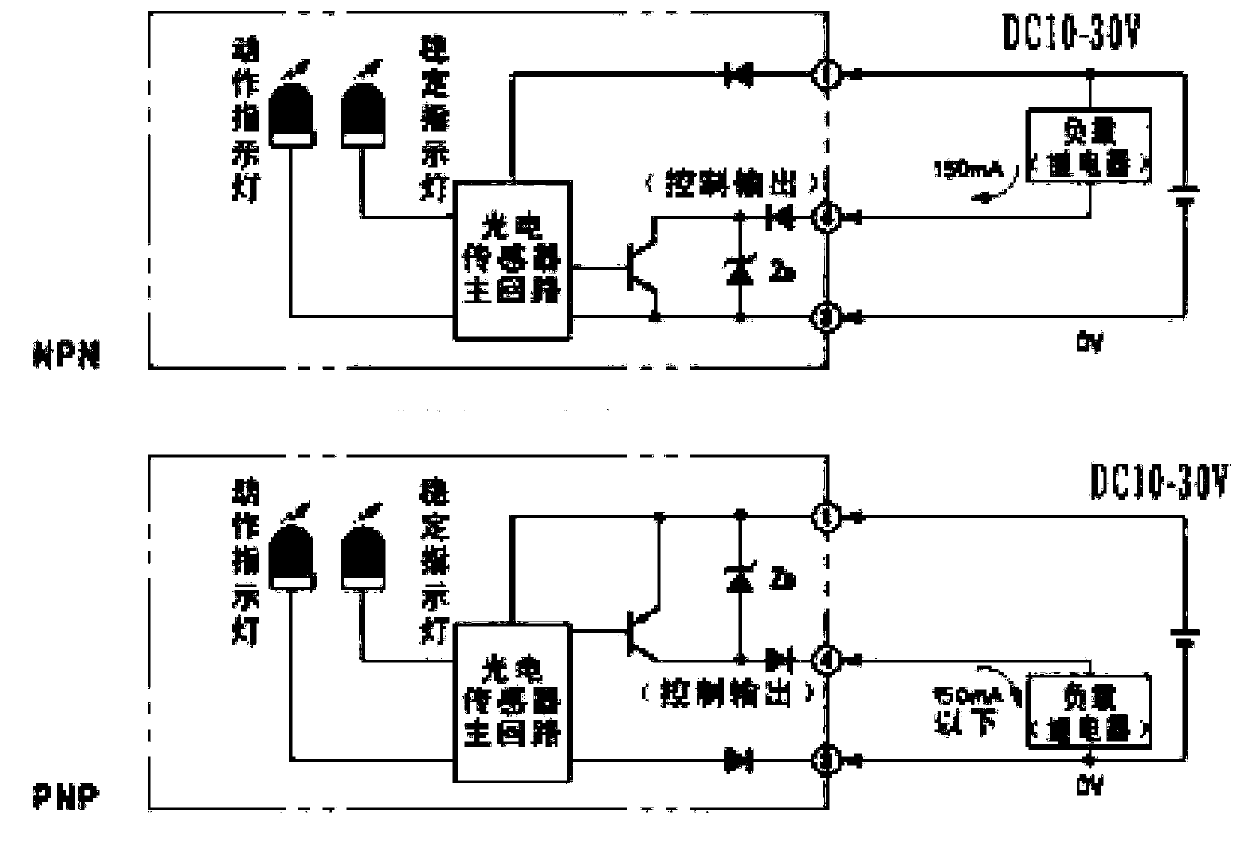
[0028] The pendulum comparison demonstration circuit includes three photoelectric switches and three counters, the control terminals of the three photoelectric switches are respectively connected to the trigger signal terminals of the three counters, and the positive and negative terminals of the power supply of the three photoelectric switches are respectively connected to the power supply The positive and negative poles of the three counters are connected to the positive and negative poles of the power supply respectively. Timing and counting circuits are integrated and modularized to reduce costs.
[0029] Further, it may also include a second timing relay, the positive terminal of the power supply of the second timing relay is connected to the positive pole of the power supply, or the positive terminal of the power supply of the second timing relay is connected to the positive pole of the power supply through a switch circuit, and the first The positive terminals of the po...
Embodiment 3
[0035] Such as figure 2As shown, this embodiment provides a pendulum comparison demonstration instrument, in addition to the pendulum comparison demonstration circuit described in the above embodiments, it also includes a display board, a pendulum and a cycloid, and the pendulum is fixed at one end of the cycloid , the other end of the cycloid is connected to the display board. The pendulum includes materials or alloys such as iron and nickel that can be adsorbed by the magnet, or it is designed to be adsorbed only on one side close to the magnetic coil. The cycloid and the pendulum are not limited to this design. Can be designed as required. The length of the cycloid, the weight of the pendulum, and the size of the pendulum angle are not limited to those shown in this design. The pendulum comparison demonstration instrument includes 2 industrial timing relays, 3 industrial counters, 3 square photoelectric switches, 7 12-volt electromagnets, 1 12-volt battery, 1 12-volt cha...
PUM
 Abstract
Description
Claims
Application Information
 - R&D Engineer
- R&D Manager
- IP Professional
- Industry Leading Data Capabilities
- Powerful AI technology
- Patent DNA Extraction
Browse by: Latest US Patents, China's latest patents, Technical Efficacy Thesaurus, Application Domain, Technology Topic, Popular Technical Reports.
© 2024 PatSnap. All rights reserved.Legal|Privacy policy|Modern Slavery Act Transparency Statement|Sitemap|About US| Contact US: help@patsnap.com