Hardware mounting structure

An installation structure and hardware technology, applied in the field of architectural decoration, can solve the problems of low installation efficiency, long installation time, cumbersome operation, etc., and achieve the effect of high installation efficiency, convenient operation, and stable structure

Pending Publication Date: 2019-08-16
SHENZHEN HOPO WINDOW CONTROL TECH CO LTD
View PDF0 Cites 0 Cited by
  • Summary
  • Abstract
  • Description
  • Claims
  • Application Information

AI Technical Summary

Problems solved by technology

[0003] However, the installation of the existing hardware transmission components in the profile groove usually adopts the groove-through installation method, which has a complex structure, cumbersome operation, long installation time, and low installation efficiency

Method used


Image

  • Hardware mounting structure
  • Hardware mounting structure
  • Hardware mounting structure

Examples


Embodiment Construction

[0035] In order to make the technical problems solved by the present invention, the technical solutions adopted and the technical effects achieved clearer, the technical solutions of the embodiments of the present invention will be further described in detail below in conjunction with the accompanying drawings. Obviously, the described embodiments are only the technical solutions of the present invention. Some, but not all, embodiments. Based on the embodiments of the present invention, all other embodiments obtained by those skilled in the art without creative efforts fall within the protection scope of the present invention.

[0036] In the description of the present invention, it should be noted that the terms "center", "upper", "lower", "left", "right", "vertical", "horizontal", "inner", "outer" etc. The indicated orientation or positional relationship is based on the orientation or positional relationship shown in the drawings, and is only for the convenience of describin...


PUM


Abstract

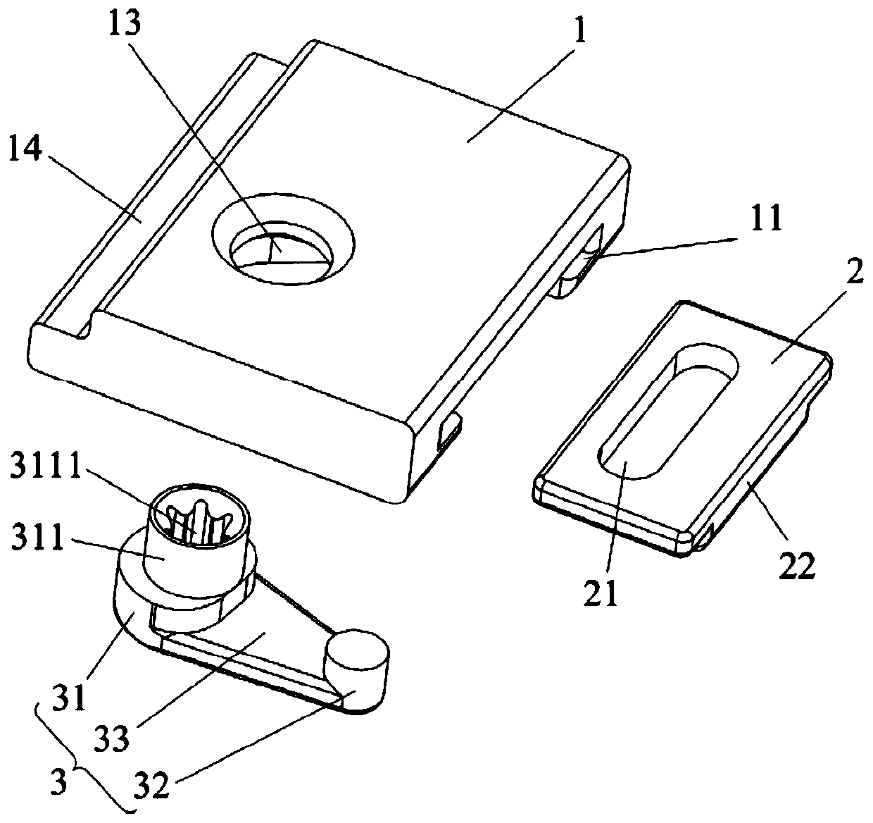
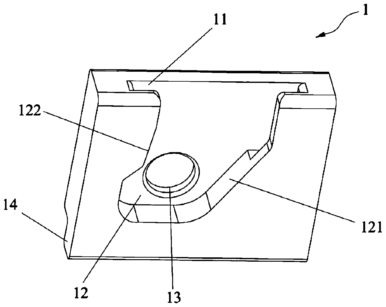
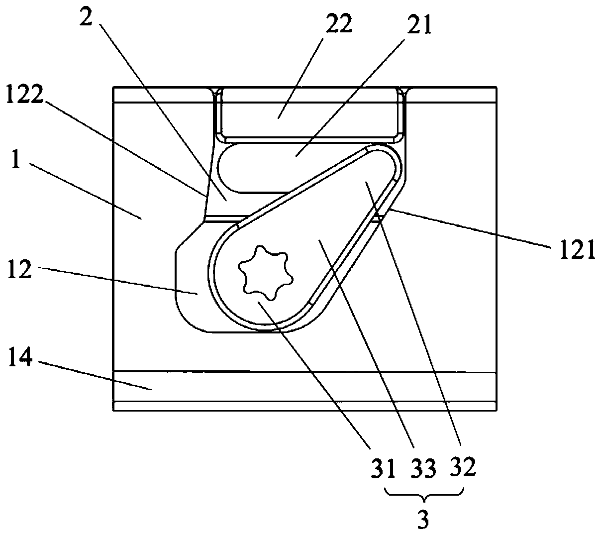
The invention relates to the technical field of building decoration, and discloses a hardware mounting structure. The hardware mounting structure comprises a base, a clamping piece and a rotating piece. The base is provided with a first sliding groove and a stop groove. The clamping piece is slidably arranged in the first sliding groove and is provided with a second sliding groove. The rotating piece is arranged in the stop groove and comprises a rotating part and a sliding part which are connected. The rotating part is rotatably connected to the base. The sliding part is slidably connected into the second sliding groove. The rotating axis of the rotating part extends in a direction perpendicular to the length direction of the second sliding groove to form a reference surface. The slidingpart can slide from one side of the reference surface to the other side of the reference surface, so that the rotating piece is attached to the inner wall of the stop groove. The hardware mounting structure is convenient to operate, simple, high in mounting efficiency, and firm, and has a self-locking function.

Description

technical field [0001] The invention relates to the technical field of architectural decoration, in particular to a hardware installation structure. Background technique [0002] In the existing door or window structure, the frame profile and the fan body profile are provided with groove structures, and the hardware transmission components are installed in the grooves of the two to form the transmission structure of the frame body and the fan body, which can realize fan The opening or locking of the body and the frame. Among them, the hardware transmission assembly includes a transmission rod, a conversion transmission part and a plurality of hardware parts. [0003] However, the installation of the existing hardware transmission components in the profile groove usually adopts the groove-through installation method. The groove-through installation method has complex structure, cumbersome operation, long installation time and low installation efficiency. Contents of the in...

Claims


Application Information

Patent Timeline
Patent Type & Authority Applications(China)
IPC IPC(8): E05B15/00E05D5/00
CPCE05B15/00E05D5/00
Inventor 高彦红黄桀颖
Owner SHENZHEN HOPO WINDOW CONTROL TECH CO LTD
Why Eureka
Try Eureka