A new type of fast self-decoupling device

A fast and new technology, applied in the direction of transportation and packaging, load suspension components, etc., can solve the problems of spring fatigue failure and high safety hazards

Active Publication Date: 2020-11-17
CHINA NUCLEAR IND ZHONGYUAN CONSTR
View PDF1 Cites 0 Cited by
  • Summary
  • Abstract
  • Description
  • Claims
  • Application Information

AI Technical Summary

Problems solved by technology

This self-decoupling hook relies on springs to achieve decoupling, and the springs are prone to fatigue and failure, which poses a high safety hazard

Method used


Image

  • A new type of fast self-decoupling device
  • A new type of fast self-decoupling device
  • A new type of fast self-decoupling device

Examples


Embodiment 1

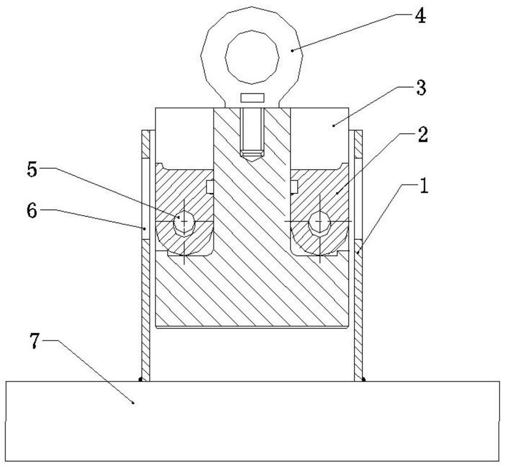
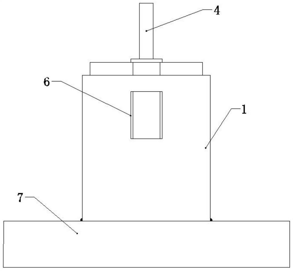
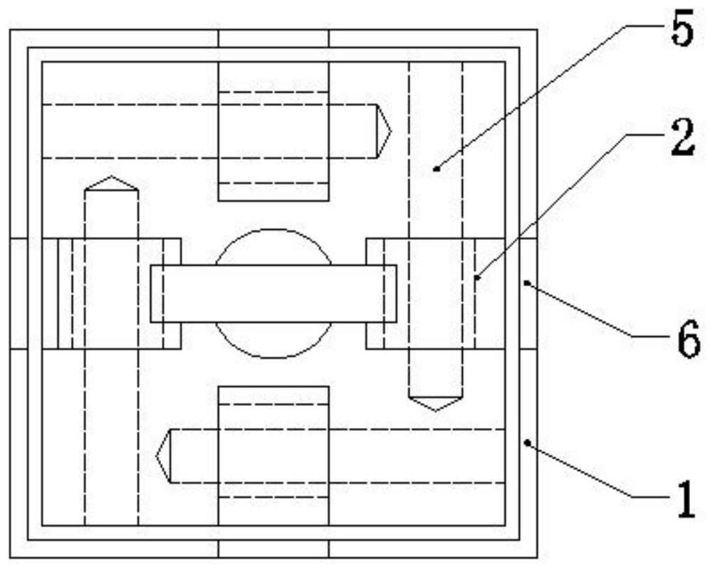
[0033] refer to Figure 1-12 As shown, this embodiment is a new type of quick self-decoupling device, which includes a column sleeve 1, a solid cylinder 3, a lifting claw 2, a lifting lug 4 and a positioning pin 5. The inside of the column sleeve 1 is provided with a cavity for the vertical displacement of the solid column 3, the upper center of the solid column 3 is fixed with a lifting lug 4, and the upper periphery of the solid column 3 is uniformly provided with a gap, and the gap is along the horizontal direction. A positioning pin 5 is fixed, and the outer side of the positioning pin 5 is provided with a hanging claw 2 that can rotate along a vertical plane.

[0034] In this embodiment, the column cover 1 is fixed on the hoisting object 7, such as by welding. The column cover 1 is a quadrangular prism, and the corresponding solid column 3 is a quadrangular prism. The lifting lug 4 is detachably connected to the solid cylinder 3 by means of screw connection.

[0035] I...

Embodiment 2

[0038] The structure and application of this embodiment are basically the same as those of Embodiment 1, the difference is that the column sleeve 1 is a cylindrical sleeve, and the solid cylinder 3 is a cylinder with notches on its periphery.

Embodiment 3

[0040] The structure and application of this embodiment are basically the same as those of the second embodiment. The column sleeve 1 is a cylindrical sleeve, and the solid cylinder 3 is a cylinder with notches on its periphery. Considering that the cylinder is easy to rotate, an anti-rotation convex key is provided in the inner cavity wall of the cylinder sleeve, and an anti-rotation key groove is provided on the outer wall of the cylinder.


PUM


Abstract

The invention discloses a novel quick self-unhooking device. The novel quick self-unhooking device comprises a column sleeve, a solid column body, lifting claws, a lifting lug and dowel pins, whereina cavity is arranged inside the column sleeve; the lifting lug is fixedly arranged on the center of the upper end of the solid column body; notches are uniformly arranged in the periphery of the upperpart of the solid column body; the dowel pins are fixedly arranged in the notches in the horizontal direction; the outer sides of the dowel pins are equipped with the lifting claws; lifting holes areuniformly formed in the periphery of the column sleeve; the column sleeve is fixedly arranged on a lifted object; strip-shaped holes are formed in the lifting claws; when the dowel pins are positioned on the lower parts of the strip-shaped holes, the lifting claws can be turned over outwards through outer-pulling force, and are exposed from the lifting holes, so that hooking is realized; and whenthe dowel pins are positioned on the upper parts of the strip-shaped holes, the lifting claws can smoothly slide out from the cavity through upward movement of the lifting lug and the solid column body, so that unhooking is realized. The device does not unhook after a lifting hook is completely dismounted, guarantees a function that equipment is unhooked after being completely and precisely placed, is simple in structure, and is convenient to use.

Description

technical field [0001] The invention relates to the technical field of self-decoupling devices, in particular to a novel fast self-decoupling device. Background technique [0002] The automatic decoupling device is generally used in loading and unloading work to avoid staff working at heights and reduce labor intensity. There are also some applications for high-altitude hoisting operations, but due to the high sensitivity of the self-decoupling device, the device will start quickly after the hook load is reduced to complete the decoupling, which cannot be fully applied to equipment high-altitude installation work. Because most of the equipment needs to be continuously adjusted when it is installed in place, the hook needs to be unloaded to a certain extent during the adjustment, and the complete unloading of the hook can only be completed after accurate alignment, so this type of installation cannot be performed for most self-decoupling devices Working hoisting operations. ...

Claims


Application Information

Patent Timeline
Patent Type & Authority Patents(China)
IPC IPC(8): B66C1/10
CPCB66C1/10
Inventor 白文奇朱建青
Owner CHINA NUCLEAR IND ZHONGYUAN CONSTR
Why Eureka
Try Eureka