Electrical impedance imaging device

An electrical impedance imaging, electrode ring technology, applied in medical science, signal transmission systems, instruments, etc., can solve problems such as screw sliding, screw tightening, and complex structure.

Pending Publication Date: 2019-08-16
NANJING INST OF RAILWAY TECH
View PDF1 Cites 0 Cited by
  • Summary
  • Abstract
  • Description
  • Claims
  • Application Information

AI Technical Summary

Problems solved by technology

[0006] In order to solve the above problems, the present invention provides an electrical impedance imaging device, which effectively avoids the complex structure of a pair of collars in the prior art, and the screw is screwed too firmly in the screw hole, which often leads to the final occurrence of screw slippage. problem flaw

Method used


Image

  • Electrical impedance imaging device
  • Electrical impedance imaging device

Examples


Embodiment Construction

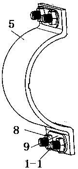
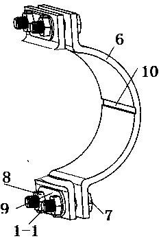
[0054] The present invention will be further described below in conjunction with the accompanying drawings and embodiments.

[0055] Such as Figure 1-Figure 2 As shown, the electrical impedance imaging device includes a water tank for electrical impedance imaging, and the water tank includes: a base, a pair of electrode rings on the base, several isolation rings stacked between the electrode rings and adjacent isolation rings. There are several new flanges between the isolation rings and between the isolation rings and the electrode rings; when the device is in use, by adjusting the use and number of the isolation rings, the height of the electrode plane relative to the bottom of the container can be adjusted, and the two electrode rings The spacing of the upper electrode plane can be adjusted from 80mm (electrode ring 40mm+2*flange 20mm) to 80mm+n×60mm (60mm=isolating ring 20mm+2*flange 20mm, n is the number of isolating rings), which can realize The effect of adjusting the...


PUM


Abstract

An electrical impedance imaging device comprises a plurality of novel flanges arranged between adjacent isolating rings and between the isolating rings and an electrode ring. Each novel flange comprises a first semicircular kit, a second semicircular kit and connecting screws, and each first semicircular kit is in threaded connection with each of the top and the bottom of the corresponding secondsemicircular kit through a pair of the connecting screws; one end of each novel flange is connected at one end of one isolating ring or the electrode ring in a sleeved manner by means of transition fit while the other end of the same is connected at one end of the other isolating ring in a sleeved manner by means of transition fit; a blocky protection block made of a plastic material is arranged between the heads of a pair of the connecting rings and the second semicircular kit and between nuts and the first semicircular kit. The defect that a pair of ferrules are comparatively complex in structure and the defect of screw thread sliding finally caused by the fact that screws are screwed too tightly in threaded holes usually in the prior art are avoided effectively.

Description

technical field [0001] The invention relates to the technical field of electrical impedance imaging, in particular to an electrical impedance imaging device. Background technique [0002] Electrical impedance imaging is a new direction of medical imaging technology. Its basic principle is to apply a small safe driving current to the human body by various methods according to the different resistance / conductivity of different tissues in the human body under different physiological and pathological conditions. / Voltage, by driving the measured response information of current or voltage in the human body, the image of the resistivity distribution or its change inside the human body is reconstructed. [0003] In other words, the electrical impedance imaging technique is an imaging technique that is sensitive to the distribution or change of the electrical impedance in the target body. Non-invasive and harmless to the human body, the system structure is simple, the measurement i...

Claims


Application Information

Patent Timeline
Patent Type & Authority Applications(China)
IPC IPC(8): A61B5/053G08C17/02G06N3/08
CPCA61B5/0536G06N3/08G08C17/02
Inventor 王啸东
Owner NANJING INST OF RAILWAY TECH
Why Eureka
Try Eureka