
Device and method for testing micro-bending loss of optical fiber in OPLC cable

A technology of micro-bending and optical fiber, which is applied in the direction of testing optical performance, testing optical fiber/optical waveguide equipment, etc. Single bending type and other problems, to achieve the effect of multiple types of micro-bending, reliable results, and high accuracy

Pending Publication Date: 2019-08-13
XI AN JIAOTONG UNIV +2
View PDF0 Cites 4 Cited by
  • Summary
  • Abstract
  • Description
  • Claims
  • Application Information

AI Technical Summary

Problems solved by technology

Similar to the fixed-diameter cylinder method, these two methods not only have relatively high cost and poor repeatability, but also lack theoretical support, and only test the microbending loss
Another example is the metal grid method and the metal grid marking line method. Although the cost is relatively low, their test microbend types are single, which is not suitable for analyzing the cause of fiber microbend loss.
[0004] Therefore, the existing methods cannot be simple and have a theoretical basis to support the testing of optical fiber microbending loss, and the existing devices lack accurate, efficient, and repeatable test models. These problems are the problems that technicians need to solve

Method used


Image

  • Device and method for testing micro-bending loss of optical fiber in OPLC cable
  • Device and method for testing micro-bending loss of optical fiber in OPLC cable
  • Device and method for testing micro-bending loss of optical fiber in OPLC cable

Examples


Embodiment Construction

[0036] The present invention will be described in detail below in conjunction with the accompanying drawings and embodiments.

[0037] first part:

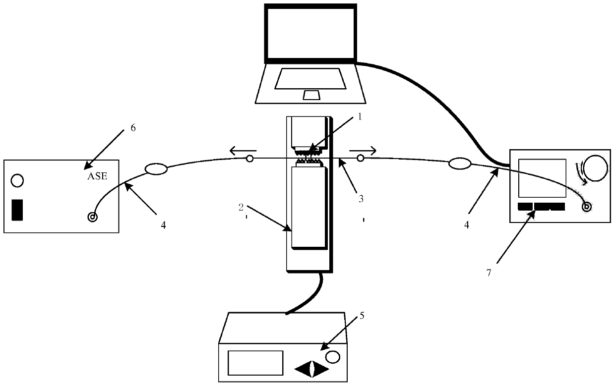
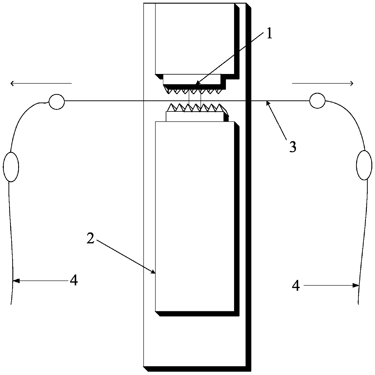
[0038] Such as Figure 1 to Figure 5 As shown, the present invention provides a device for testing optical fiber microbending loss in OPLC cables, including multiple types and pairs of optical fiber microbending models 1, displacement platforms 2, single-mode optical fibers to be tested 3, and optical fiber jumpers 4. The displacement platform controller 5, the light source 6 and the optical power meter 7. During the test, the precise control of the displacement platform 2 is realized through the displacement platform controller 5 on the computer. , get different optical powers, and store them on the computer.

[0039] the second part:

[0040] Adopt the method for different types of microbend loss of optical fiber in the OPLC cable of device test of the present invention, the required equipment is according to such as image...


PUM


Abstract

The invention discloses a device and method for testing micro-bending loss of an optical fiber in an OPLC cable. The device comprises a micro-bending model of the optical fiber, an optical power meterand the like. When testing, the micro-bending model is set on a displacement platform, the single-mode optical fiber to be tested passes through the micro-bending model of the optical fiber, and a displacement platform controller is used to adjust the displacement of the displacement platform such that the single-mode optical fiber is sandwiched between the fixed end and the movable end of the displacement platform; both ends of the single-mode optical fiber are respectively connected to the light source and the optical power meter through an optical fiber jumper, and movement of the displacement platform is used to obtain different optical powers stored on the computer. The device and method provided by the invention accurately manufacture a plurality of micro-bending models through 3D printing technology, and solve the problem that the existing micro-bending test method is difficult to achieve accuracy, high efficiency and repeatability. The matched movement of the displacement platform and the micro-bending model is controlled by the computer, and the single-mode optical fiber is squeezed with different precisions to achieve different micro-bending effects, so that the technical problems lacking experimental and theoretical basis in the prior art are solved.

Description

technical field [0001] The invention belongs to the technical field of optical fiber detection, and in particular relates to a device and method for testing optical fiber microbend loss in OPLC cables. Background technique [0002] The power fiber-to-the-home project based on optical fiber composite low-voltage cable (OPLC) utilizes power channel resources to realize the deep integration of power grid and communication network infrastructure, which is an effective way to realize energy Internet information communication. However, the optical fiber in the OPLC cable works under the superimposed conditions of thermal field and stress field for a long time, and the attenuation and degradation of the optical fiber directly affect the transmission capacity of the optical fiber and the service life of the OPLC. However, there is currently a lack of research on the attenuation characteristics of the optical fiber in the OPLC cable in this superimposed environment, and it is necessa...

Claims


Application Information

Patent Timeline
Patent Type & Authority Applications(China)
IPC IPC(8): G01M11/02
CPCG01M11/33
Inventor 陈玉姚凯孙冠姝阿森·阿什法克葛维春罗桓桓周桂平于晶郭毅伏丽娜
Owner XI AN JIAOTONG UNIV
Learn More