
Fully automatic tube sheet welding tooling platform

A tube sheet welding, fully automatic technology, applied in welding equipment, auxiliary welding equipment, welding/cutting auxiliary equipment, etc., can solve the problems of time-consuming, time-consuming and labor-intensive

Active Publication Date: 2020-10-02
合肥哈工库讯智能科技有限公司
View PDF13 Cites 0 Cited by
  • Summary
  • Abstract
  • Description
  • Claims
  • Application Information

AI Technical Summary

Problems solved by technology

[0002] In welding practice teaching, as well as in international and domestic welding skill competitions, welding operation positions are in various forms, such as horizontal welding, flat welding, vertical welding, overhead welding, oblique 45° welding position, flat fillet welding and vertical fillet welding etc., and the angles of welding are also different. In the existing welding teaching and training tooling, manual clamps are usually used to clamp the weldment through bolt fixing, positioning and locking. During this process, the welding operator has to complete The adjustment, assembly, positioning, and clamping of the workpiece position are very inefficient. In a teaching class, it takes a lot of time to position the weldment, especially in the limited time when the competition time is tight, only clamping the workpiece It takes a lot of time for the players, and because the assembly accuracy is adjusted manually, the welding accuracy is also very low, and the position of the weldment needs to be adjusted and fixed manually, and the labor intensity is also very high.

Method used


Image

  • Fully automatic tube sheet welding tooling platform
  • Fully automatic tube sheet welding tooling platform
  • Fully automatic tube sheet welding tooling platform

Examples


Embodiment Construction

[0036] Specific embodiments of the present invention will be described in detail below in conjunction with the accompanying drawings. It should be understood that the specific embodiments described here are only used to illustrate and explain the present invention, and are not intended to limit the present invention.

[0037] In the present invention, unless otherwise specified, the orientation words included in the term such as "up, down, left, right, front, back, inside and outside" only represent the orientation of the term in the normal use state, or the common name understood by those skilled in the art. , and should not be construed as a limitation of this term.

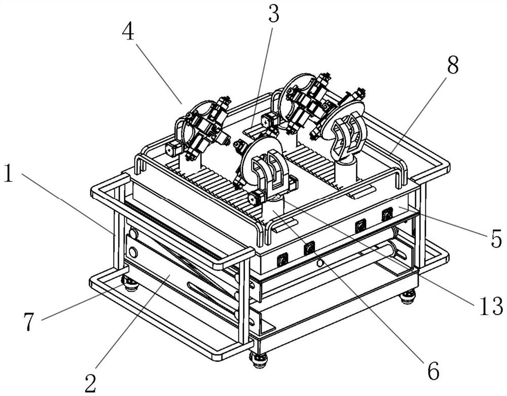
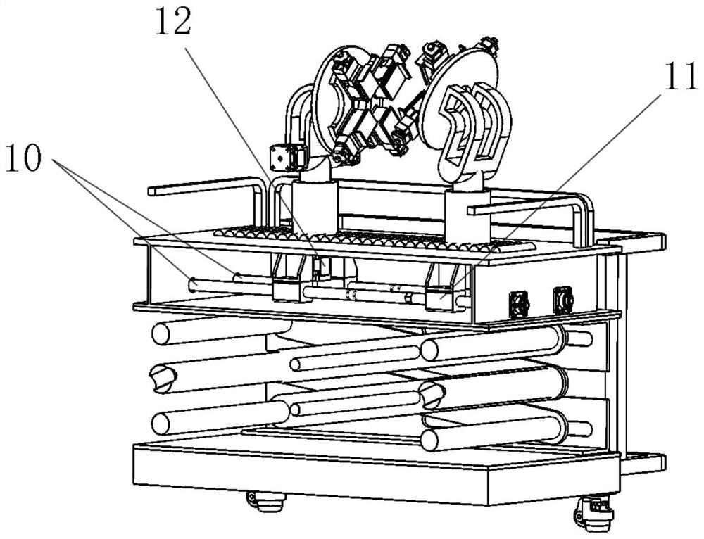
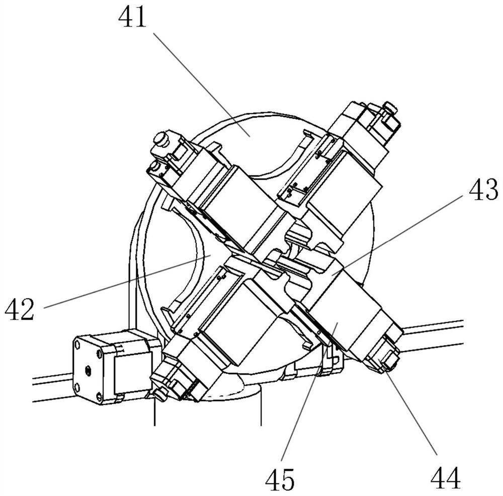
[0038] see Figure 1-6 The full-automatic tube-sheet welding tooling platform shown, the full-automatic tube-sheet welding tooling platform includes a frame 1, a workbench is arranged on the frame 1, an organic box 5 is arranged under the workbench, and an arrangement is arranged on the workbench There are a ...


PUM


Abstract

The invention discloses a full-automatic tube sheet welding tool platform. A working table is provided with a plurality of strip-shaped track grooves, tube sheet clamping mechanisms are arranged in the strip-shaped track grooves correspondingly, and a drive mechanism is arranged in a machine box; the upper end of a curvy swing arm is fixedly connected with a round disc, and the lower end of the curvy swing arm is movably hinged to a telescopic mechanism; a rotating shaft penetrates through the round disc, a clamp base sleeves the rotating shaft, and the clamp base is provided with a pluralityof clamping servo drive modules in a radiation mode; the first side of a L-shaped clamping block is located at the tip of the telescopic movable end, the second side of the L-shaped clamping block islocated on the side surface of the side, back to the round disc, of the telescopic movable end, and the second side of the L-shaped clamping block is further fixedly connected with a clamping stop block. The full-automatic tube sheet welding tool platform is used for welding practical teaching of tube sheets and tube sheets, plates and plates and the tube sheets and the plates, the welding assembling efficiency and welding assembly precision are improved, the labor intensity is relieved, welding operators quickly clamp workpieces in practical teaching and welding skill competitions, and the welding position is flexibly adjusted for welding operation.

Description

technical field [0001] The invention relates to a positioning and clamping device for welding parts in welding practice teaching and welding skill competitions, in particular to a fully automatic tube-sheet welding tooling platform. Background technique [0002] In welding practice teaching, as well as in international and domestic welding skill competitions, welding operation positions are in various forms, such as horizontal welding, flat welding, vertical welding, overhead welding, oblique 45° welding position, flat fillet welding and vertical fillet welding etc., and the angles of welding are also different. In the existing welding teaching and training tooling, manual clamps are usually used to clamp the weldment through bolt fixing, positioning and locking. During this process, the welding operator has to complete The adjustment, assembly, positioning, and clamping of the workpiece position are very inefficient. In a teaching class, it takes a lot of time to position t...

Claims


Application Information

Patent Timeline
Patent Type & Authority Patents(China)
IPC IPC(8): B23K37/04B23K37/00B23K101/06
CPCB23K37/006B23K37/0435B23K37/0461B23K2101/06
Inventor 张帅谋肖传芳张婧赵祯李国强阮砚珏
Owner 合肥哈工库讯智能科技有限公司
Learn More