Combustion equipment

A combustion equipment and combustion chamber technology, applied in burners, combustion methods, combustion control and other directions, can solve the problems of waste gas discharge to pollute the environment, insufficient gas combustion, low energy conversion, etc., to avoid pollution, easy operation, and reduce nitrogen. Effect of sulfur content

Inactive Publication Date: 2019-08-06
诸暨市斯博申机电设备设计有限公司
View PDF5 Cites 0 Cited by
  • Summary
  • Abstract
  • Description
  • Claims
  • Application Information

AI Technical Summary

Problems solved by technology

[0002] With the development of science and technology and the progress of society, industrial manufacturing has always occupied a relatively large position in the gross national product. The country actively promotes the development of high technology. Other equipment that release energy are common in traditional manufacturing and daily life, such as internal combustion engines, boilers, fuel generators, etc. These traditional combustion equipment, due to their complex design, lead to cumbersome operations and uneven mixing of oil and gas, resulting in energy conversion Low, insufficient gas combustion, exhaust gas pollution and other shortcomings are often criticized by people
In order to achieve the advantages of high efficiency, automation, simplification and cleanliness in industrial manufacturing and daily life, traditional equipment can no longer meet the needs of existing industrial manufacturing and daily life. Therefore, it is necessary to design an automated, integrated, and operational Simple, efficient and pollution-free combustion equipment, this device effectively solves the above problems

Method used


Image

  • Combustion equipment
  • Combustion equipment

Examples


Embodiment Construction

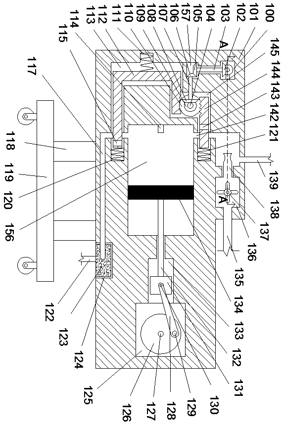
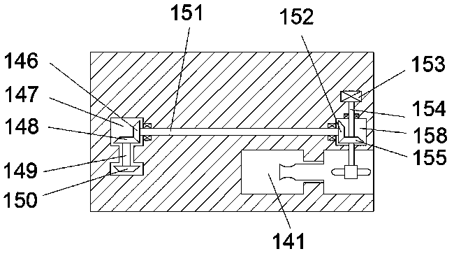
[0017] Combine below Figure 1-2 The present invention is described in detail, wherein, for the convenience of description, the orientations mentioned below are defined as follows: figure 1 The up, down, left, right, front and back directions of the projection relationship itself are the same.

[0018] refer to Figure 1-2 , a combustion device of the present invention, comprising a body 101 and a first gear meshing chamber 100 extending forward and backward inside the body 101, a fan power assembly is arranged in the first gear meshing chamber 100, and the first The right side of a gear meshing chamber 100 is provided with an oil-air mixing chamber 141, and the right side of the oil-air mixing chamber 141 is communicated with a fan chamber 136, and the oil-air mixing chamber 141 and the fan chamber 136 are jointly provided with an oil-air mixing assembly. The fan power assembly provides working power for the oil-air mixing assembly. A second gear engagement chamber 157 is p...


PUM


Abstract

The invention provides combustion equipment. The equipment comprises a machine body and a first gear meshing cavity, wherein the first gear meshing cavity is arranged in the machine body and extends forwards and backwards, a fan power assembly is arranged in the first gear meshing cavity, an oil-gas mixing cavity is formed in the right side of the first gear meshing cavity, the right side of the oil-gas mixing cavity communicates with a fan cavity, oil-gas mixing assemblies are arranged in the oil-gas mixing cavity and the fan cavity, and the fan power assembly provides working power for the oil-gas mixing assemblies; a second gear meshing cavity is formed below the first gear meshing cavity, an oil-gas discharging-into power assembly is arranged in the second gear meshing cavity, the right side of the second gear meshing cavity is provided with an oil-gas discharging-into controlling cavity extending upwards and downwards, and an oil-gas discharging-into controlling assembly is arranged in the oil-gas discharging-into controlling cavity. According to the equipment, through the mechanical transmission cooperation, the working efficiency of the equipment is improved, the working rhythm is ordered, the design is compact, the equipment is light, the energy is saved, and the environment is protected.

Description

technical field [0001] The invention relates to the technical field of combustion power, in particular to a combustion device. Background technique [0002] With the development of science and technology and the progress of society, industrial manufacturing has always occupied a relatively large position in the gross national product. The country actively promotes the development of high technology. Other equipment that release energy are common in traditional manufacturing and daily life, such as internal combustion engines, boilers, fuel generators, etc. These traditional combustion equipment, due to their complex design, lead to cumbersome operations and uneven mixing of oil and gas, resulting in energy conversion Low, insufficient gas combustion, exhaust gas pollution and other shortcomings are often criticized by people. In order to achieve the advantages of high efficiency, automation, simplification and cleanliness in industrial manufacturing and daily life, traditio...

Claims


Application Information

Patent Timeline
Patent Type & Authority Applications(China)
IPC IPC(8): F23D11/10F23D11/40F23N5/22F23J15/02F23K5/02
CPCF23D11/10F23D11/40F23J15/025F23K5/02F23N5/22
Inventor 徐晶晶
Owner 诸暨市斯博申机电设备设计有限公司
Why Eureka
Try Eureka