
Manhole device and vacuum heat insulation low-temperature storage tank with manhole device

A technology for vacuum insulation and low-temperature storage tanks, which is applied to fixed-capacity gas storage tanks, installation devices of container structures, outer walls of container structures, etc. The need for tank inspection and the effect of ensuring vacuum tightness

Pending Publication Date: 2019-07-26
ZHANGJIAGANG CIMC SANCTUM CRYOGENIC EQUIP +2
View PDF0 Cites 1 Cited by
  • Summary
  • Abstract
  • Description
  • Claims
  • Application Information

AI Technical Summary

Problems solved by technology

[0004] However, in the design of the existing vacuum insulated cryogenic storage tanks, due to the need to ensure the vacuum environment of the interlayer between the inner and outer tanks, there is no structure similar to a manhole, so a vacuum insulated storage tank without a manhole structure cannot Satisfy the inspection requirements for tank entry proposed by the IGC rules and the rules of various classification societies

Method used


Image

  • Manhole device and vacuum heat insulation low-temperature storage tank with manhole device
  • Manhole device and vacuum heat insulation low-temperature storage tank with manhole device
  • Manhole device and vacuum heat insulation low-temperature storage tank with manhole device

Examples


Embodiment Construction

[0049] Typical embodiments embodying the features and advantages of the present invention will be described in detail in the following description. It should be understood that the present invention can have various changes in different embodiments without departing from the scope of the present invention, and that the description and drawings therein are illustrative in nature and not intended to limit the present invention. invention.

[0050] In the following description of various exemplary embodiments of the invention, reference is made to the accompanying drawings, which form a part hereof, and in which are shown by way of example different exemplary structures, systems, and embodiments in which aspects of the invention may be implemented and steps. It is to be understood that other specific arrangements of components, structures, exemplary means, systems and steps may be utilized and structural and functional modifications may be made without departing from the scope o...


PUM


Abstract

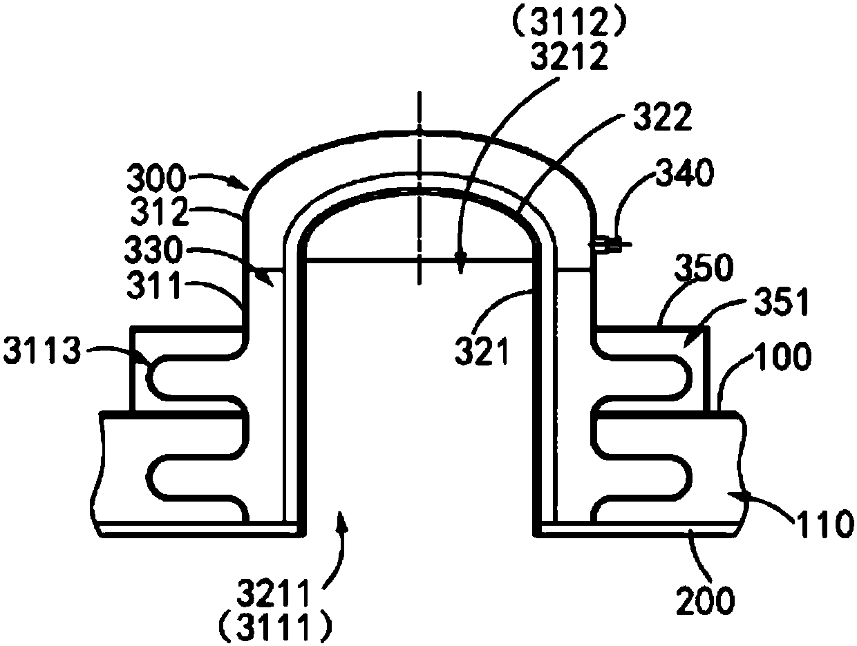
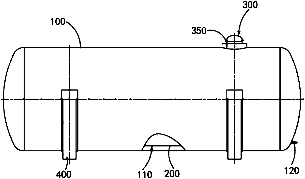
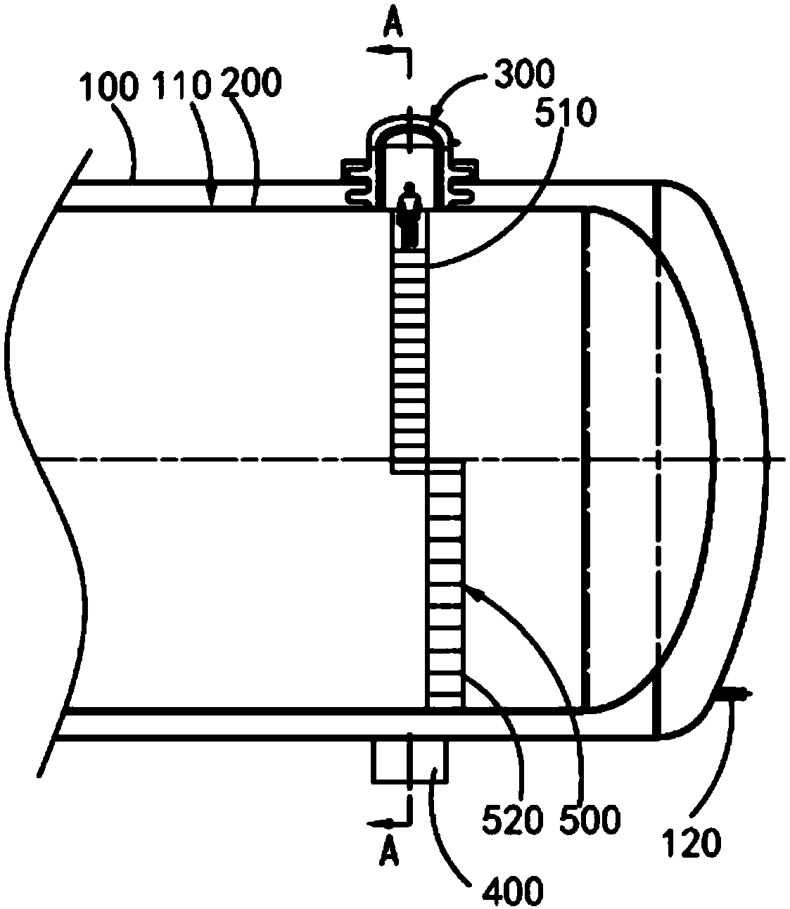
The invention discloses a manhole device and a vacuum heat insulation low-temperature storage tank with the manhole device. The vacuum heat insulation low-temperature storage tank comprises an outer shell and an inner container arranged in the outer shell, and a third interlayer with the vacuum environment is formed between the outer shell and the inner container. The manhole device comprises an outer hole assembly and an inner hole assembly. The outer hole assembly comprises an outer barrel and an outer cover. The outer barrel is provided with a first barrel port and a second barrel port, wherein the first barrel port is connected to the outer wall of the inner container, and the second barrel port stretches out of the outer shell. The outer cover is arranged on the second barrel port inan opening and closing manner. The inner hole assembly comprises an inner barrel and an inner cover. The inner barrel is sleeved with the outer barrel and provided with a third barrel port and a fourth barrel port, the third barrel port communicates with the inner container, and the fourth barrel port corresponds to the second barrel port. The inner cover is arranged on the fourth barrel port in an opening and closing manner. The outer diameter of the inner barrel is smaller than the inner diameter of the outer barrel, a first interlayer is formed between the outer hole assembly and the innerhole assembly, and the outer barrel is provided with a vacuum pumping port so that the first interlayer can be subjected to vacuum pumping.

Description

technical field [0001] The invention relates to the technical field of cryogenic pressure vessels, in particular to a manhole device and a vacuum insulated cryogenic storage tank having the manhole device. Background technique [0002] When liquefied natural gas (LNG) is used as fuel, it has the environmental protection characteristics of low sulfur content. In areas such as ships or offshore platforms, the use of liquefied natural gas as fuel has become increasingly common. Since the boiling point of liquefied natural gas at normal pressure is -162°C, how to store and transport it safely and reliably is an important link when using liquefied natural gas as a ship fuel. Generally speaking, liquefied natural gas is more suitable to be stored in vacuum insulated cryogenic storage tanks to obtain a longer maintenance time and minimize the loss of liquefied natural gas. [0003] According to the IGC rules, vacuum insulation cryogenic storage tanks belong to Type C independent ...

Claims


Application Information

Patent Timeline
Patent Type & Authority Applications(China)
IPC IPC(8): F17C1/12F17C13/00F17C13/06
CPCF17C1/12F17C13/00F17C13/06F17C2205/0379F17C2203/0391
Inventor 刘东进范洪军顾华甘少炜徐小艳李晓晨尹红伟黄乾
Owner ZHANGJIAGANG CIMC SANCTUM CRYOGENIC EQUIP
Learn More