
Conveyor bridges and conveying equipment with tunnel conveyors and conveyor bridges

A technology for conveying equipment and conveyors, applied in the direction of conveyors, conveyor objects, transportation and packaging, etc., can solve problems such as disassembly troubles, and achieve the effect of simplifying installation and disassembly

Active Publication Date: 2022-07-08
ROBERT BOSCH GMBH
View PDF11 Cites 0 Cited by
  • Summary
  • Abstract
  • Description
  • Claims
  • Application Information

AI Technical Summary

Problems solved by technology

[0005] If the last-mentioned solution offers the advantage of a high load-carrying capacity of the bridging set, its removal in the event of a fault on the bridging set proves to be cumbersome

Method used


Image

  • Conveyor bridges and conveying equipment with tunnel conveyors and conveyor bridges
  • Conveyor bridges and conveying equipment with tunnel conveyors and conveyor bridges
  • Conveyor bridges and conveying equipment with tunnel conveyors and conveyor bridges

Examples


Embodiment Construction

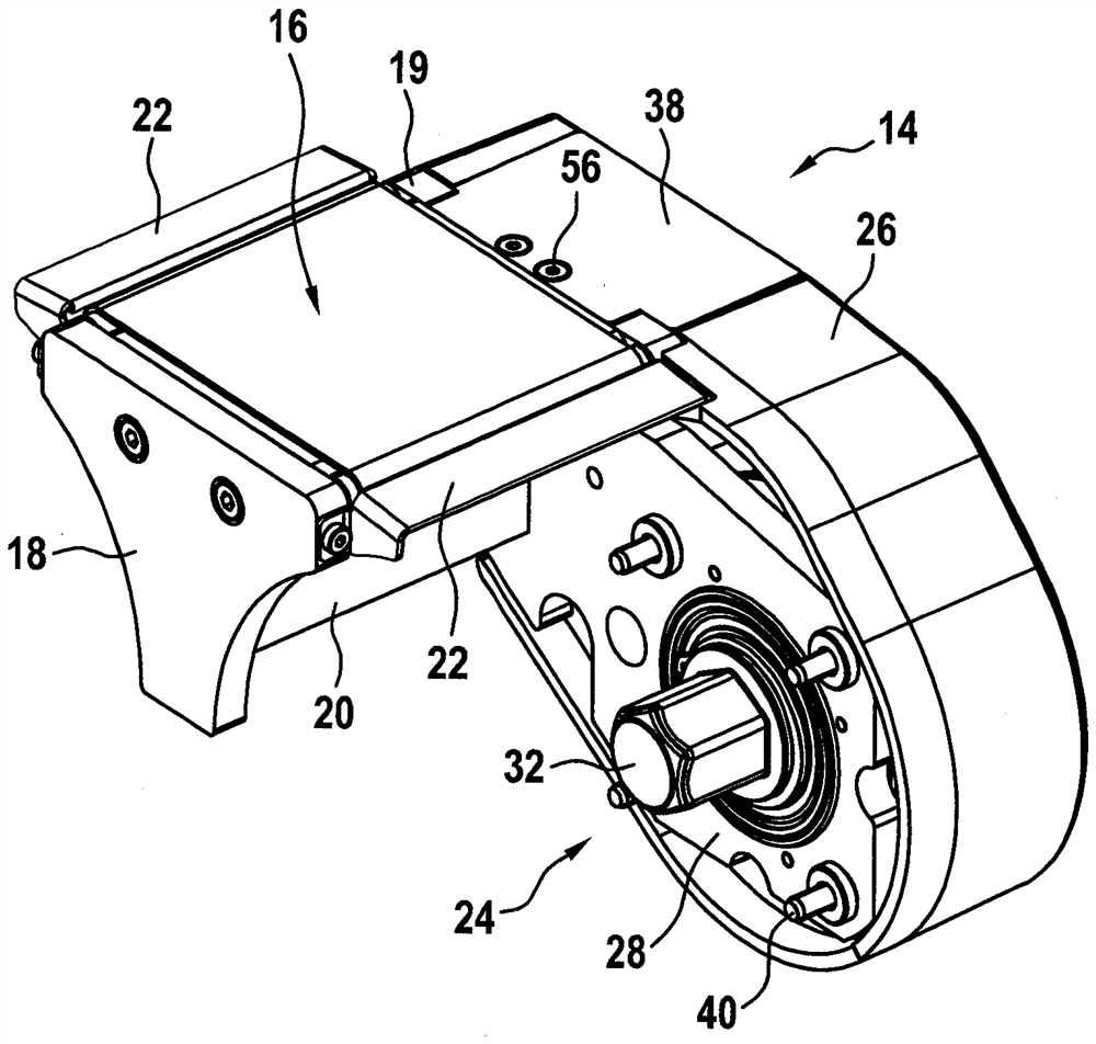
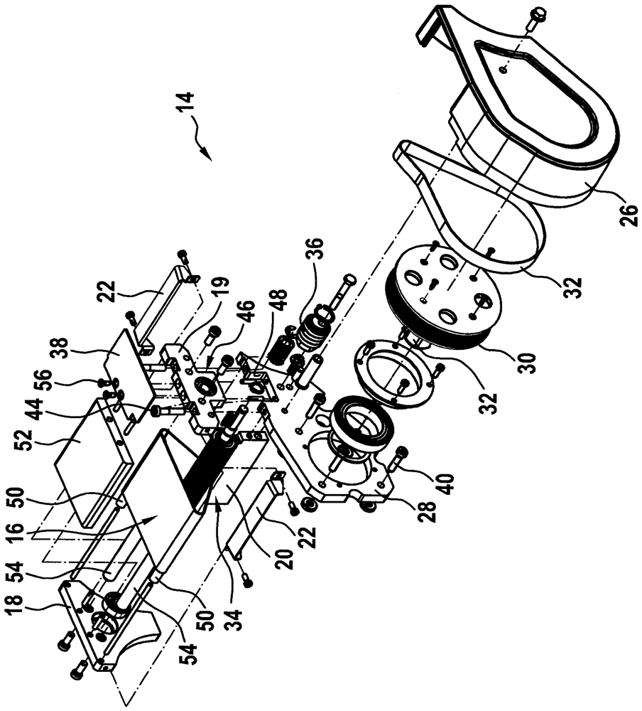
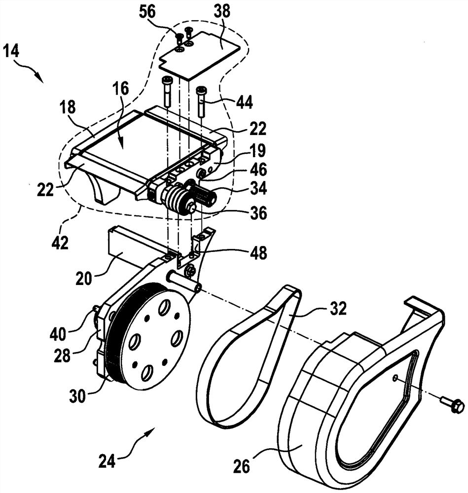
[0041] according to figure 1 , the conveying device 1 has a road conveyor 2 configured as a chain conveyor. exist figure 1 Only one chain conveyor 2 is shown, which has conveying means 4 designed as chains, which continuously rotate on a frame 6 of the chain conveyor 2 . The frame 6 is supported on a number of columns 8 at the bottom. the chain 4 in its figure 1 The upper side shown in is used for conveying a conveying material (not shown). The conveyed material rests on the chain 4 during operation. The chain 4 is designed in such a way that it can be bent not only in a direction normal to the conveying plane but also in a direction parallel to the conveying plane. The first-mentioned flexibility is used in the region of the end section 10 of the chain conveyor 2 to deflect the chain 4 and to guide it back, and the last-mentioned flexibility is The reversing of the road conveyor 2 can be realized, for example, in the region of the bend 12 .

[0042] The conveying devic...


PUM


Abstract

A conveying bridge for bridging conveying trenches on end sections of road conveyors is disclosed, the conveying bridge having a rotatably supported drive shaft and a drive shaft coupled thereto to be rotatable or circumferential The conveying device used for conveying materials is supported in the way. Furthermore, a conveying device with a tunnel conveyor and such a conveying bridge is disclosed.

Description

technical field [0001] The invention relates to a conveying bridge and a conveying device having a tunnel conveyor and a conveying bridge. Background technique [0002] For conveying material along largely fixed lines, roadway conveyors are suitable. The road conveyor can be constructed, for example, in a belt-like structure with flat belts as conveying means or in a chain-like structure with a large number of elements which are inserted into one another in the form of links. When switching from one road conveyor to the next road conveyor or processing station, so-called conveying troughs are created, which are caused by the fact that the rotating conveying means must be deflected there by a radius. In order to prevent the conveyed material from falling into the conveying channel, remaining there or even being damaged or caught, connecting groups or bridging parts with their own conveying means are known. The connecting group or the bridging element closes the gap of the c...

Claims


Application Information

Patent Timeline
Patent Type & Authority Patents(China)
IPC IPC(8): B65G47/52B65G15/24B65G47/66
CPCB65G47/52B65G15/24B65G47/66B65G21/06
Inventor P.路德维希F.舒马歇尔-库茨H-P.布陶
Owner ROBERT BOSCH GMBH
Learn More