Electronic tape measure

A tape measure and electronic technology, applied in the direction of bendable rulers, measuring devices, instruments, etc., can solve problems such as slipping, tape pulling out too fast, lost steps, etc., achieve high measurement accuracy, realize real-time reading, and avoid slipping Effect

Pending Publication Date: 2019-07-09
SHENZHEN DOBIY LASER CO LTD
View PDF7 Cites 3 Cited by
  • Summary
  • Abstract
  • Description
  • Claims
  • Application Information

AI Technical Summary

Problems solved by technology

However, in actual use, because the user often pulls out the tape too quickly, this type of tape is often prone to slipping and lost steps when calculating the length of the tape, which greatly affects the measurement results and measurement accuracy. Wait

Method used


Image

  • Electronic tape measure
  • Electronic tape measure
  • Electronic tape measure

Examples


Embodiment 1

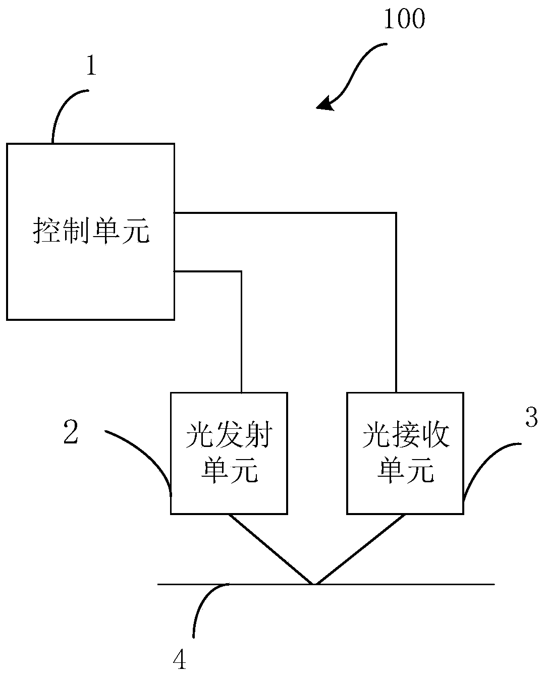
[0036] Please refer to figure 1 with figure 2 , the embodiment of the present invention proposes an electronic tape measure 100, which can be applied to length measurement in different occasions. The measured length can be read in real time through the electronic tape measure 100 , and problems such as slippage and step loss caused by the tape being pulled out too fast can be well solved. The structure of the electronic tape measure 100 will be described in detail below.

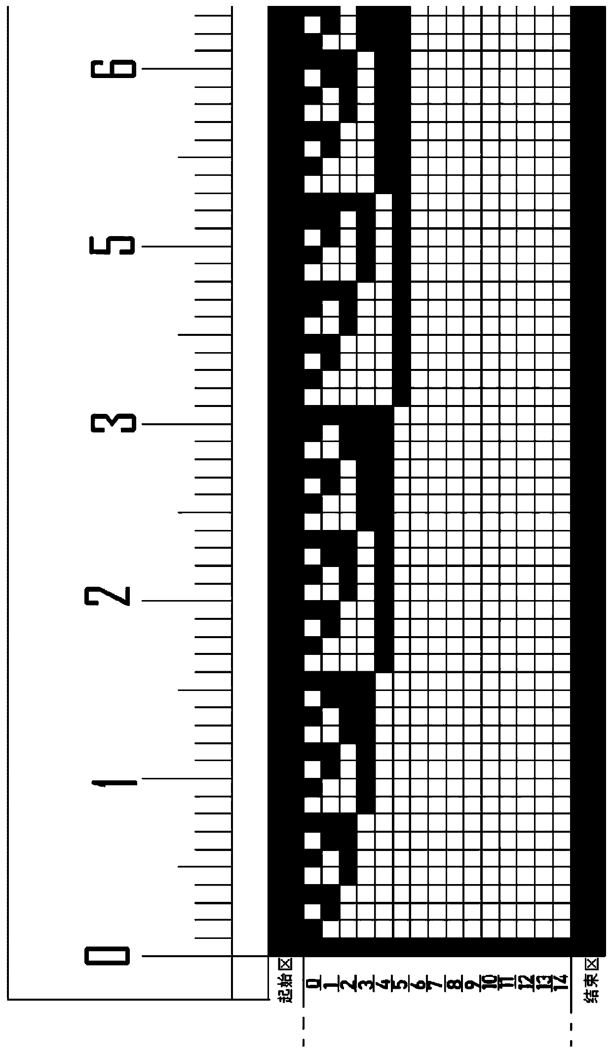
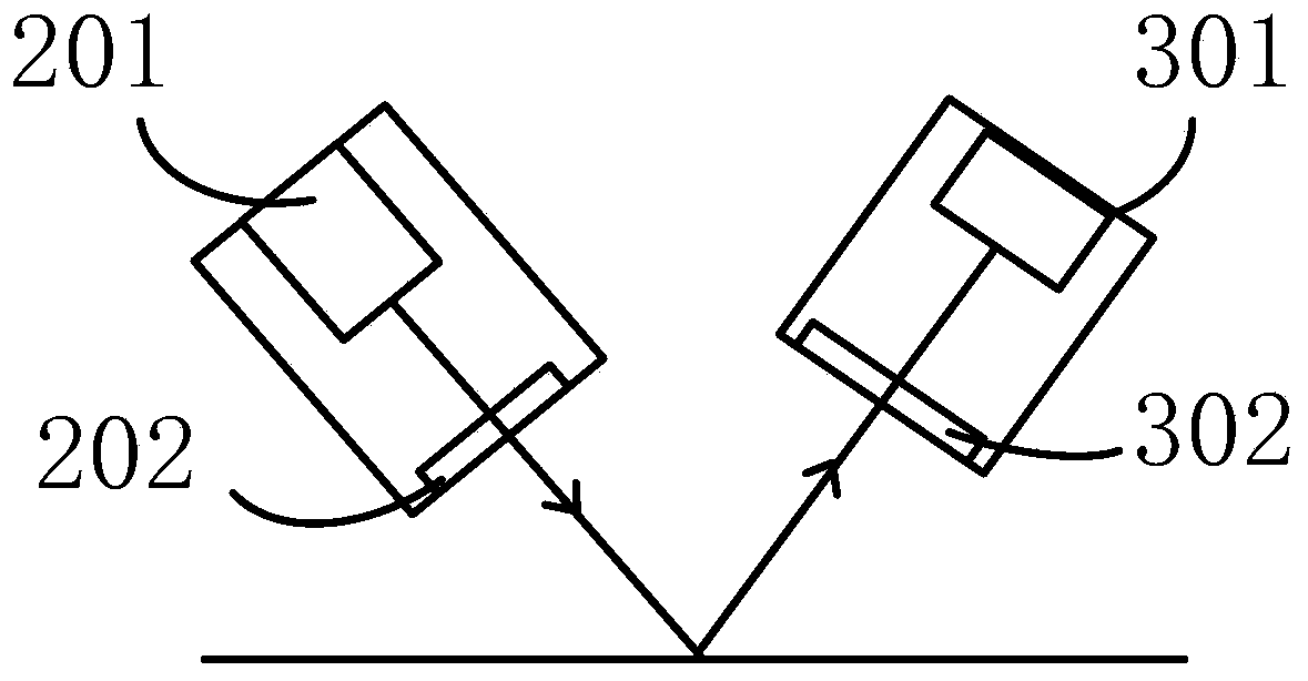
[0037] Such as figure 1 As shown, the electronic tape measure 100 mainly includes a control unit 1 , a light emitting unit 2 , a light receiving unit 3 and a tape 4 , wherein the length of a target can be measured through the tape 4 . In the embodiment of the present invention, the tape 4 is provided with a plurality of different image units, and each image unit corresponds to a minimum scale of the tape 4 and represents a preset length, such as figure 2 shown.

[0038] It can be understood that each ...


PUM


Abstract

The invention provides an electronic tape measure. The electronic tape measure comprises: a control unit, a light emitting unit, a light receiving unit and a tape band, wherein the tape band is provided with a plurality of different image units, each of the image units corresponds to a minimum scale of the tape band and indicates a predetermined length, and the light emitting unit is configured toemit light onto the image units; the light receiving unit is configured to receive an optical signal reflected by the image units and convert the optical signal into an electrical signal; and the control unit is configured to determine a measured length according to the electrical signal. Compared with the existing scheme of reading the tape measure by using a photoelectric sensor or a Hall sensor, the electronic tape measure provided by the invention can realize real-time reading of the tape band data, can avoid problems such as slipping and losing steps and the like, and ensure relatively high measurement accuracy, etc.

Description

technical field [0001] The invention relates to the field of tape measures, in particular to an electronic tape measure. Background technique [0002] With the development of modern electronic technology, length measurement has gradually realized digitalization and intelligence. For electronic tapes that appear on the market, most of them still use Hall sensors, photoelectric sensors and other devices, as well as rotating devices used in conjunction with tapes. Pulse counting to realize the automatic measurement of tape. However, in actual use, because users often pull out the ruler tape too quickly, this type of tape measure is often prone to slipping and lost steps when calculating the length of the ruler tape, which greatly affects the measurement results and measurement accuracy. Wait. Contents of the invention [0003] In view of this, the object of the present invention is to provide an electronic tape measure in order to overcome the deficiencies in the prior art....

Claims


Application Information

Patent Timeline
Patent Type & Authority Applications(China)
IPC IPC(8): G01B3/10
CPCG01B3/1061G01B3/1069
Inventor 王振兴张新文
Owner SHENZHEN DOBIY LASER CO LTD
Why Eureka
Try Eureka