Image compensation method, device and computer storage medium

An image compensation and imaging technology, applied in the field of image compensation, can solve problems such as the increase of image displacement error, and achieve the effect of reducing image displacement deviation and geometric distortion

Active Publication Date: 2021-07-20
HARBIN INST OF TECH
View PDF6 Cites 0 Cited by
  • Summary
  • Abstract
  • Description
  • Claims
  • Application Information

AI Technical Summary

Problems solved by technology

[0004] And for the above geometric distortion, such as image 3 As shown in , from the center O of the area to be imaged to both ends, due to the existence of the curvature of the earth, the resulting image displacement error gradually increases

Method used


Image

  • Image compensation method, device and computer storage medium
  • Image compensation method, device and computer storage medium
  • Image compensation method, device and computer storage medium

Examples


Embodiment Construction

[0034] The following will clearly and completely describe the technical solutions in the embodiments of the present invention in conjunction with the accompanying drawings in the embodiments of the present invention.

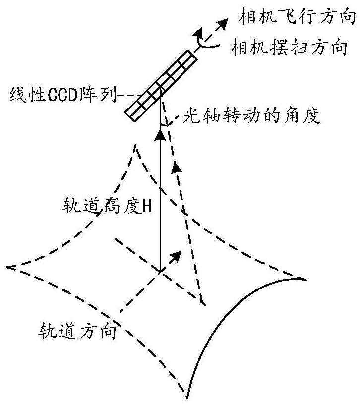
[0035] For an example of an optical imaging satellite at orbital altitude H, see figure 1 , which shows the process of conventional ground sweep imaging, in figure 1 In the optical imaging satellite, the load of the optical imaging satellite is an optical camera composed of a linear CCD array. The CCD array scans the ground area for imaging; this scanning imaging process can specifically be visible light scanning imaging, and finally a complete image of the target area can be obtained by splicing the image strips obtained by scanning at different times.

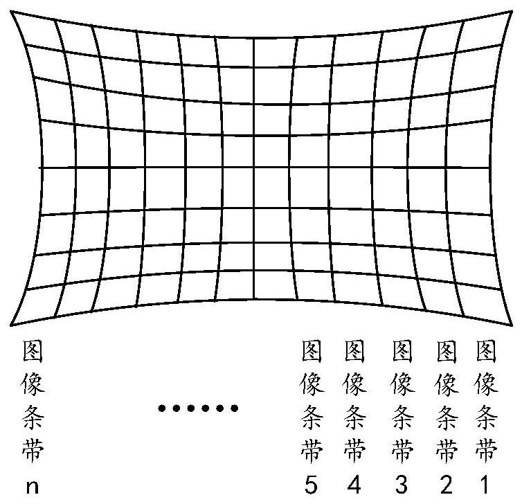
[0036] Through the elaboration of the above imaging process, the images finally scanned are spliced ​​from the image strip 1, image strip 2, and image strip n obtained by the linear CCD array sweep respectivel...


PUM


Abstract

The embodiment of the present invention discloses an image compensation method, device, and computer storage medium; the method may include: dividing a linear charge-coupled device CCD array into a plurality of CCD line segments; The current relative angle between the target area and each of the CCD line segments determines the current to-be-rotated angle of each of the CCD line segments; for each of the CCD line segments, the rotation is performed according to the current to-be-rotated angle of each of the CCD line segments ; The region to be imaged is photographed through the rotated CCD line segment.

Description

technical field [0001] The present invention relates to the technical field of aerospace observation, in particular to an image compensation method, device and computer storage medium. Background technique [0002] Swing-sweep imaging refers to a dynamic imaging method that performs imaging simultaneously during satellite attitude maneuvering. The satellite camera quickly reaches a certain angular velocity in the rolling direction, and then moves at a certain angular velocity to image the ground. A linear charge-coupled device (CCD, Charge-Coupled Device) array is often used in sweep imaging, specifically, as figure 1 As shown, a certain number of CCD photosensitive elements are arranged in a straight line, and the CCD array in this layout form is called a linear CCD array, also known as a scanning CCD. By scanning with a linear CCD array and splicing the remote sensing images acquired at each moment, a large-format high-resolution visible light image can be obtained. [0...

Claims


Application Information

Patent Timeline
Patent Type & Authority Patents(China)
IPC IPC(8): H04N5/225H04N5/232H04N5/372
CPCH04N23/54H04N23/60H04N25/71
Inventor 曹喜滨王峰李宁金光徐伟
Owner HARBIN INST OF TECH
Why Eureka
Try Eureka