Foldable photovoltaic power generation mechanism
A photovoltaic power generation and photovoltaic panel technology, applied in the field of foldable photovoltaic power generation mechanism, can solve the problems of time-consuming construction and inconvenient movement
- Summary
- Abstract
- Description
- Claims
- Application Information
AI Technical Summary
Problems solved by technology
Method used
Image
Examples
specific Embodiment approach 1
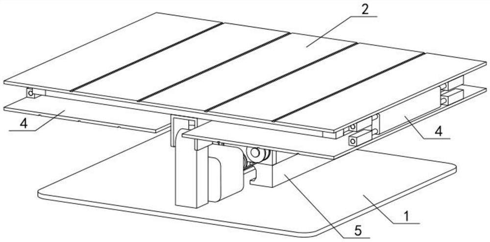
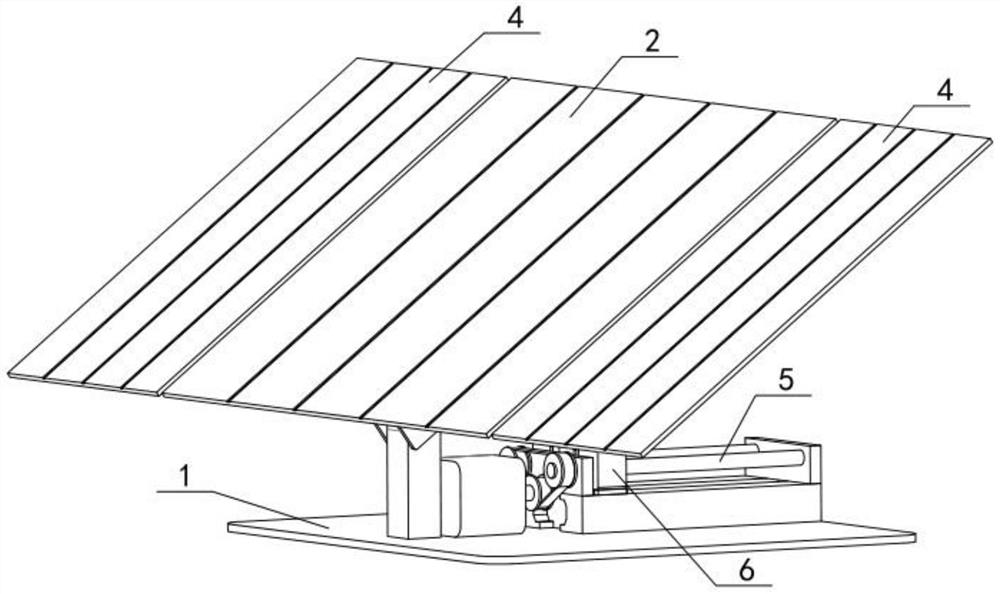
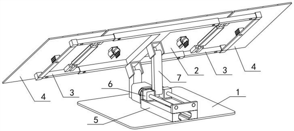
[0030] Such as Figure 1-10 As shown, the foldable photovoltaic power generation mechanism includes an installation base 1, a photovoltaic panel I2, a telescopic frame 3, a photovoltaic panel II4, a track 5, a displacement member 6 and a connecting rod 7, and the installation base 1 is rotatably connected with a photovoltaic panel I2, The left and right sides of the photovoltaic panel Ⅰ2 are slidingly connected with the telescopic frame 3, the photovoltaic panel Ⅱ4 is rotatably connected with the photovoltaic panel Ⅰ2, the track 5 is fixedly connected to the installation base 1, the track 5 and the installation base 1 are connected by belt transmission, and the displacement member 6 is connected to the installation base 1. The track 5 is slidably connected, the displacement member 6 is rotatably connected to one end of the connecting rod 7 , and the other end of the connecting rod 7 is rotatably connected to the photovoltaic panel I2.
specific Embodiment approach 2
[0032] Such as Figure 1-10 As shown, the installation base 1 includes a touch plate 1-1, a bearing seat 1-2, a motor 1-3 and a pulley I1-4, and the rear end of the touch plate 1-1 is fixedly connected with a bearing seat 1-2 , The motor 1-3 is fixedly connected to the touch plate 1-1, and the pulley I1-4 is fixedly connected to the output shaft of the motor 1-3. The height of the bearing seat 1-2 should meet the requirement that when the inclination angle of the main body of the photovoltaic panel I2-9 reaches the maximum value, when the main body of the photovoltaic panel II4-1 is turned and displayed, the main body of the photovoltaic panel II4-1 will not touch the floor 1 -1, used to make the photovoltaic panel main body II4-1 rotate 180 degrees smoothly.
specific Embodiment approach 3
[0034] Such as Figure 1-10 As shown, the photovoltaic panel I2 includes a connecting part I2-1, a square tube 2-2, an installation hole I2-3, an installation hole II2-4, an axle seat I2-5, an axle I2-6, an axle seat II2-7, Shaft II 2-8, photovoltaic panel main body I 2-9, connecting sleeve I 2-10, first connecting sleeve II 2-11 and snap handle 2-12, the front and rear ends of the connecting part I 2-1 are fixedly connected with square tubes 2 -2, the lower ends of the left side of the two square tubes 2-2 are provided with installation holes I2-3, the lower ends of the two square tubes 2-2 on the right are provided with installation holes II2-4, and the shaft seats I2- 5. It is fixedly connected in the middle of the lower end of the square tube 2-2 at the rear end. The shaft seat I2-5 is fixedly connected with the shaft I2-6. The shaft seat II2-7 is fixedly connected to the front side of the lower end of the connecting part I2-1. The shaft seat Ⅱ2-7 is fixedly connected wit...
PUM
 Abstract
Description
Claims
Application Information
 - R&D
- Intellectual Property
- Life Sciences
- Materials
- Tech Scout
- Unparalleled Data Quality
- Higher Quality Content
- 60% Fewer Hallucinations
Browse by: Latest US Patents, China's latest patents, Technical Efficacy Thesaurus, Application Domain, Technology Topic, Popular Technical Reports.
© 2025 PatSnap. All rights reserved.Legal|Privacy policy|Modern Slavery Act Transparency Statement|Sitemap|About US| Contact US: help@patsnap.com


