
Connecting structure for heat exchanger

A connection structure and heat exchanger technology, applied in the direction of heat exchange equipment, heat exchanger type, heat exchanger shell, etc., can solve the problems of inconvenient fixing and installation, inconvenient use, single function, etc., to achieve easy installation and fixing, The effect of avoiding liquid leakage and stabilizing the connection structure

Inactive Publication Date: 2019-07-02
WUXI JIUSHENG HEAT EXCHANGER
View PDF0 Cites 0 Cited by
  • Summary
  • Abstract
  • Description
  • Claims
  • Application Information

AI Technical Summary

Problems solved by technology

[0002] A heat exchanger is a device that transfers part of the heat of a hot fluid to a cold fluid, also known as a heat exchanger. Heat exchangers play an important role in chemical, petroleum, power, food and many other industrial productions. Heat exchangers can be used as heaters, coolers, condensers, evaporators, reboilers, etc., and are widely used. Shell-and-tube heat exchangers are mainly composed of shells, tube bundles, tube sheets, and heads. Round shape with parallel tube bundles or spiral tubes inside. Take a heat exchanger with parallel tube bundles inside as an example. Since the tube bundles are long, there needs to be a connecting structure between the tube bundles to fix them to avoid deviation. ,

Method used


Image

  • Connecting structure for heat exchanger
  • Connecting structure for heat exchanger
  • Connecting structure for heat exchanger

Examples


Example Embodiment

[0016] The technical solutions in the embodiments of the present invention will be clearly and completely described below in conjunction with the accompanying drawings in the embodiments of the present invention. Obviously, the described embodiments are only a part of the embodiments of the present invention, rather than all the embodiments. Based on the embodiments of the present invention, all other embodiments obtained by those of ordinary skill in the art without creative work shall fall within the protection scope of the present invention.

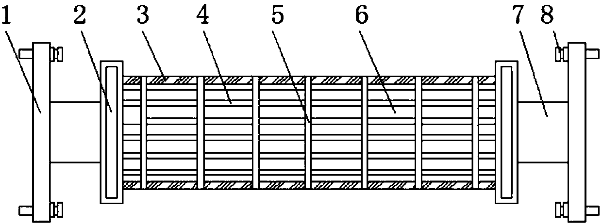
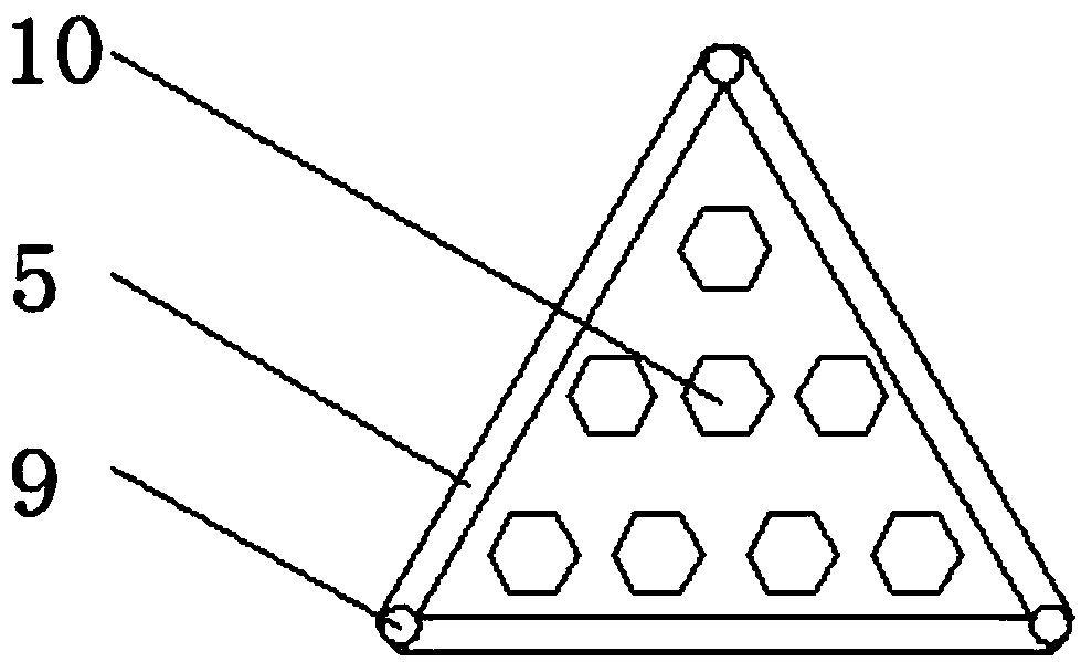
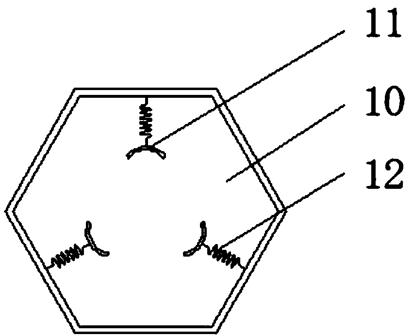
[0017] See Figure 1-5 , An embodiment provided by the present invention: a connection structure for a heat exchanger, comprising a partition plate 5, a tube bundle body 6, a return spring 12, and a reserved groove 16. The tube bundle body 6 is uniformly provided with reinforcing ribs 3 and heat exchange The tube 4 and the partition plate 5, the longitudinal section of the partition plate 5 is honeycomb, so that the strength of the parti...


PUM

PropertyMeasurementUnit
Angleaaaaaaaaaa

Abstract

The invention discloses a connecting structure for a heat exchanger. The connecting structure comprises partition plates, a tube bundle main body, a returning spring and pre-reserved grooves; reinforcing ribs, heat exchange tubes and the partition plates are uniformly disposed on the tube bundle main body; cavities are formed in the two ends of the tube bundle main body correspondingly; the pre-reserved grooves are uniformly formed in the sides, close to the tube bundle main body, of the interiors of the cavities; connecting pipes are disposed at the ends, far away from the tube bundle main body, of the cavities correspondingly; flange plates are installed at the ends, far away from the tube bundle main body, of the connecting pipes correspondingly; the heat exchange tubes transversely penetrate through hoops correspondingly; the two ends of the heat exchange tubes are connected with the pre-reserved grooves correspondingly; O-shaped seal rings are disposed in the connecting positionsof the heat exchange tubes and the pre-reserved grooves correspondingly; moving rings are disposed at the ends, close to the tube bundle main body, of the O-shaped seal rings correspondingly; and stationary rings are disposed at the ends, far away from the tube bundle main body, of the O-shaped seal rings correspondingly. By installing the flange plates and fixing bolts, a device is convenient toinstall, fix and use.

Description

technical field [0001] The invention relates to the technical field of connection structures, in particular to a connection structure for heat exchangers. Background technique [0002] A heat exchanger is a device that transfers part of the heat of a hot fluid to a cold fluid, also known as a heat exchanger. Heat exchangers play an important role in chemical, petroleum, power, food and many other industrial productions. Heat exchangers can be used as heaters, coolers, condensers, evaporators, reboilers, etc., and are widely used. Shell-and-tube heat exchangers are mainly composed of shells, tube bundles, tube sheets, and heads. Round shape with parallel tube bundles or spiral tubes inside. Take a heat exchanger with parallel tube bundles inside as an example. Since the tube bundles are long, there needs to be a connecting structure between the tube bundles to fix them to avoid deviation. , the traditional connection structure is not easy to fix and install, and it is more t...

Claims


Application Information

Patent Timeline
IPC IPC(8): F28D7/16F28F9/12F28F9/26
CPCF28D7/16F28F9/12F28F9/26
Inventor 赵雪荣
Owner WUXI JIUSHENG HEAT EXCHANGER
Learn More