


Quick Research
Generate reliable direction feasibility study reports for your R&D in just a few steps.

Technical Q&A
Discover and master advanced knowledge NOW. Basics, ideas, possibilities, all at once.

Find Solutions
As an expert in R&D theories, this can generate solutions to your technical problems instantly.

Evaluate Feasibility
Analyze your overall solution with one click, know your potential R&D risks in advance.

Monitor Landscape
Get weekly tech updates, stay abreast of the latest tech innovations and key insights.
Motor shaft with location pin
A motor shaft and locating pin technology, applied in electrical components, electromechanical devices, electric components, etc., can solve problems such as motor shaft and fan slippage
- Summary
- Abstract
- Description
- Claims
- Application Information
AI Technical Summary
Problems solved by technology
Method used
Image

Examples
Embodiment Construction
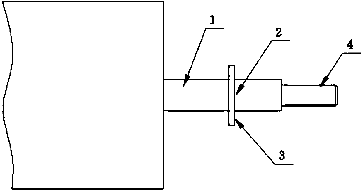
[0012] refer to figure 1 , the present invention provides a motor shaft with positioning pins, comprising: a motor shaft body 1, the motor shaft body 1 is provided with a through groove 2, and a positioning pin 3 is installed in the through groove 2 with an interference fit, The length of the positioning pin 3 is greater than the outer diameter of the motor shaft body 1 , and the motor shaft body 1 is coaxially provided with a threaded fixing portion 4 .
[0013] In this embodiment, the motor shaft with positioning pins is fixedly connected to the external fan blades through the positioning pins and the threaded fixing portion, which can carry a relatively large load, and there will be no slipping between the motor shaft and the fan blades to cause failure.
[0014] The above is only a preferred embodiment of the present invention, it should be pointed out that for those of ordinary skill in the art, without departing from the technical principle of the present invention, some...
PUM
 Abstract
Description
Claims
Application Information
 - R&D Engineer
- R&D Manager
- IP Professional
- Industry Leading Data Capabilities
- Powerful AI technology
- Patent DNA Extraction
Browse by: Latest US Patents, China's latest patents, Technical Efficacy Thesaurus, Application Domain, Technology Topic, Popular Technical Reports.
© 2024 PatSnap. All rights reserved.Legal|Privacy policy|Modern Slavery Act Transparency Statement|Sitemap|About US| Contact US: help@patsnap.com