
Photophoretic trap projection system and method

A projection system and trap technology, applied in the field of virtual imaging, can solve the problem that the observer cannot see the whole picture of the object intuitively.

Active Publication Date: 2019-06-28
悠游笙活(北京)网络科技有限公司
View PDF8 Cites 0 Cited by
  • Summary
  • Abstract
  • Description
  • Claims
  • Application Information

AI Technical Summary

Problems solved by technology

However, these images have a disadvantage, that is, they cannot allow the observer to see the whole picture of the object intuitively in space.

Method used


Image

  • Photophoretic trap projection system and method
  • Photophoretic trap projection system and method
  • Photophoretic trap projection system and method

Examples


Embodiment Construction

[0059] In order to make the object, technical solution and advantages of the present invention clearer, the present invention will be further described in detail below in combination with specific embodiments and with reference to the accompanying drawings. It should be understood that these descriptions are exemplary only, and are not intended to limit the scope of the present invention. Also, in the following description, descriptions of well-known structures and techniques are omitted to avoid unnecessarily obscuring the concept of the present invention.

[0060] Explanation of technical terms:

[0061] Volumetric image: Volumetric image refers to the "suspension" virtual image of an object in real space, which can present the shape and color value of most of the surface of the object.

[0062] Photophoretic phenomenon: Tiny particles (about 5 microns) suspended in the air will move in the direction of weak light when they are irradiated by strong light. The gravitational ...


PUM


Abstract

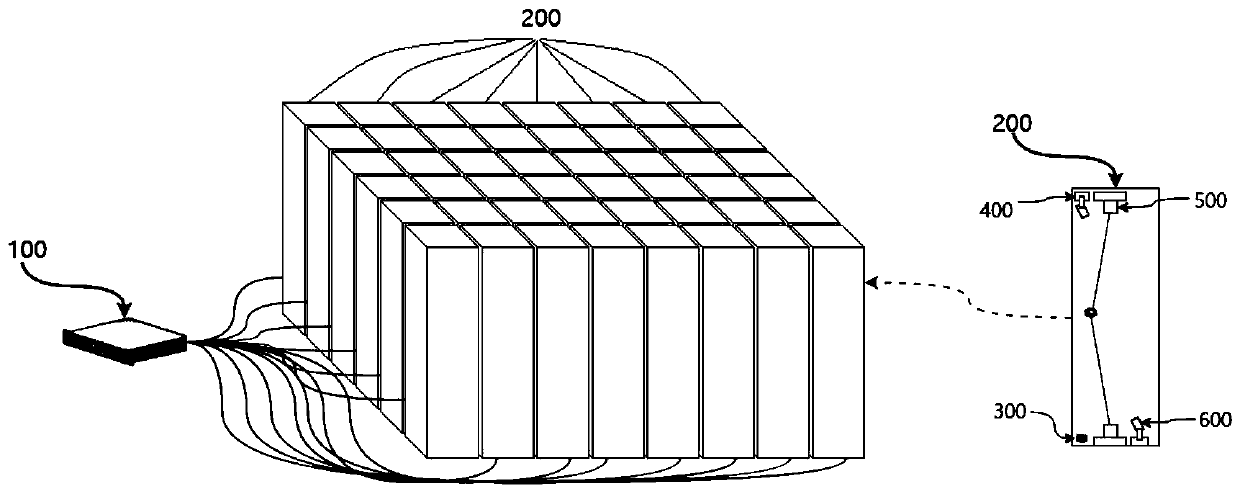
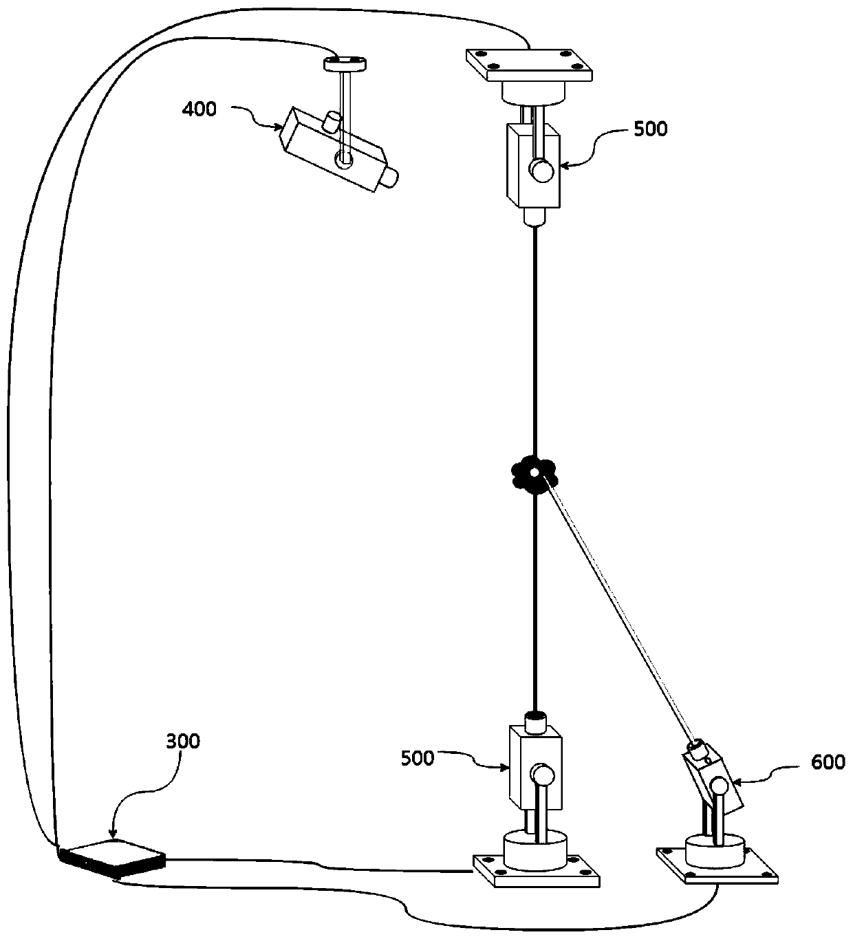
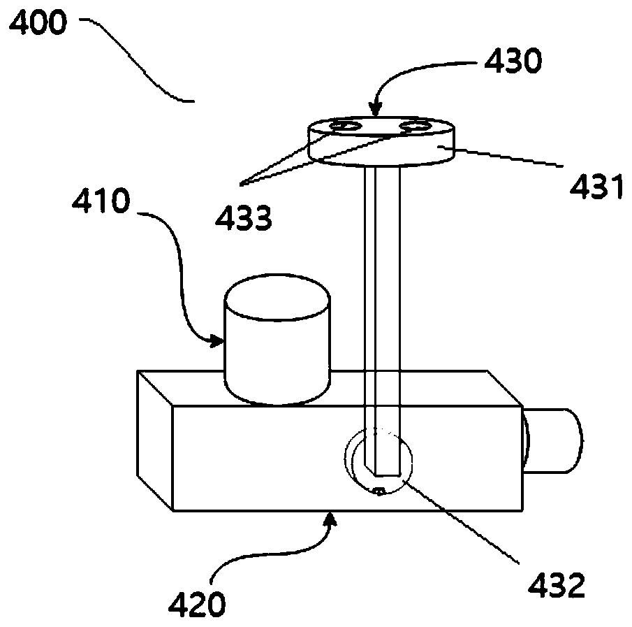
The invention relates to a photophoretic trap projection system and a photophoretic trap projection method. The projection system comprises a volume body image splitting device and a plurality of volume body image projectors. The volume body image splitting device splits a first 3D model into a plurality of second 3D models and sends the second 3D models to the corresponding volume body image projectors. Each volume body image projector comprises a volume body image projection control device, a particle emitting device, a photophoresis trap control device and a particle coloring device. The particle emitting device emits particles into the photophoretic trap when no particles exist in the photophoretic trap. The photophoresis trap control device controls the position of the photophoresis trap so as to control the movement track of the particles. The particle coloring device is used for coloring particles, and finally a virtual object which is basically consistent with an original object in standing in space is achieved. According to the scheme, the continuous and large-size projection 3D model can be displayed.

Description

technical field [0001] The invention relates to the technical field of virtual imaging, in particular to a photophoretic trap projection system and method. Background technique [0002] Holographic imaging technology (or 3D imaging technology) has been widely used all over the world. But at present, these technologies still use 2-dimensional media (for example: optical interference screen, optical film, etc.) to display a 3-dimensional object image. The user can only observe the image at a specific observation position, and cannot go around to the back of the image to see the backlight part of the object. [0003] In the prior art, methods such as high-speed rotating prisms and laminated screens can display holographic images of objects at a certain angle in a very small closed entity (for example, in a space the size of a box). However, these images have a disadvantage, that is, they cannot allow the observer to see the whole picture of the object intuitively in space. ...

Claims


Application Information

Patent Timeline
IPC IPC(8): G03H1/22G06T17/00H04N13/30
Inventor 郭润泽彭璐
Owner 悠游笙活(北京)网络科技有限公司
Learn More