Auxiliary unloading device for light truck

A technology for auxiliary unloading devices and trucks, applied to vehicles with chains/belts, etc., can solve the problems of increased labor costs, low efficiency, and slow speed, and achieve low labor costs, high efficiency, and fast unloading speed Effect

Pending Publication Date: 2019-06-28
山西机电职业技术学院
View PDF0 Cites 0 Cited by
  • Summary
  • Abstract
  • Description
  • Claims
  • Application Information

AI Technical Summary

Problems solved by technology

[0003] Light trucks can be loaded with loaders, excavators and other equipment, which is very convenient, but when unloading, because light trucks are not equipped with hydraulic lifting devices, they cannot be unloaded by tilting the bucket. However, due to the large bucket of the loader, it is impossible to operate in the body of the light truck, so the unloading of the light truck is usually done manually, which will greatly increase the labor cost, and the speed is slow and the efficiency is low.

Method used


Image

  • Auxiliary unloading device for light truck
  • Auxiliary unloading device for light truck
  • Auxiliary unloading device for light truck

Examples


Embodiment 1

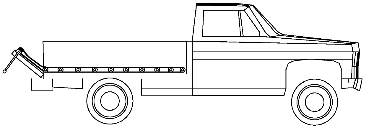
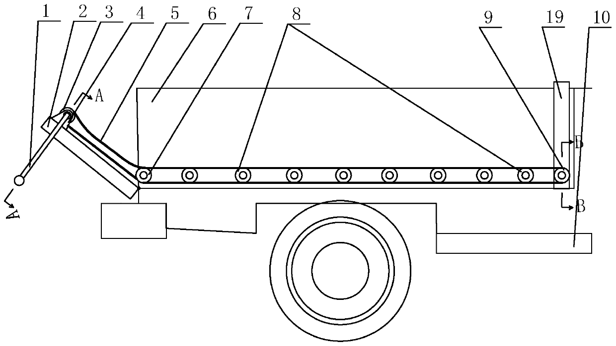
[0037] Such as Figure 1-Figure 4 As shown, the light truck auxiliary unloading device of the present invention,

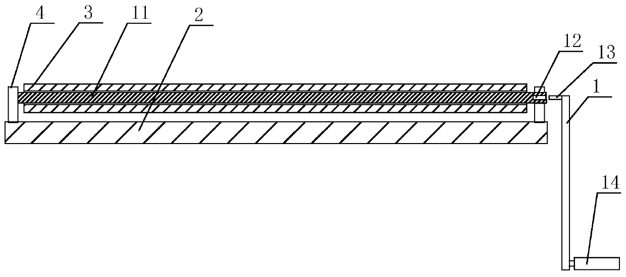
[0038] Including the conveying mechanism, the conveying mechanism includes the driving roller 3, the driven roller 9, the supporting roller 8, the reversing roller 7 and the conveyor belt 5. The rotating shaft 11 of the driving roller 3 is installed on the axle seat 4, and the axle seat 4 is fixed on the tail of the car body On the upper part of the inner wall of the door 2, a driven roller 9 is provided at the front end of the vehicle body, a reversing roller 7 is provided at the rear end of the vehicle body, and a number of support rollers 8 are provided between the reversing roller 7 and the driven roller 9, between the driving roller 3 and the driven roller A conveyor belt 5 is wound on the moving roller 9, and the reversing roller 7 and the supporting roller 8 are in a closed space formed by the conveyor belt 5;

[0039] It includes a transmission mechanism. The t...

Embodiment 2

[0046] Such as Figure 5-Figure 12 As shown, as another preferred solution, the transmission mechanism includes a runner 20. A groove is provided on the side of the runner 20. The runner 20 is in the shape of a pulley. A square rod 13 is fixed at the axis of the end face of the runner 20. The holes 12 are matched, and the rope 26 is wrapped around the groove of the runner 20. Pulling the rope 26 can make the runner 20 rotate, the runner 20 drives the driving roller 3 to rotate, and the driving roller 3 drives the conveyor belt 5 to rotate, thereby unloading the material. The support roller 8 plays the role of supporting the conveyor belt 5, preventing the conveyor belt 5 from being crushed by the material, which cannot be supported by manpower during unloading, and even causing the conveyor belt 5 to wear.

[0047] A fixing device is included. The fixing device includes a positioning rod 23, the lower end of the positioning rod 23 is sharp, and the upper end of the positioning r...


PUM


Abstract

The invention relates to an auxiliary loading device of a light truck and belongs to the field of automobiles. The auxiliary loading device comprises a conveying mechanism, wherein the conveying mechanism comprises a driving roller, a driven roller, a supporting roller, a reversing roller and a conveying belt, wherein a rotating shaft of the driving roller is mounted on a shaft seat, the shaft seat is fixed to the upper portion of the inner wall of a car hopper tail door, the driven roller is arranged at the front end of a car hopper, a reversing roller is arranged at the tail end of the car hopper, and a plurality of supporting rollers are arranged between the reversing roller and the driven roller. The conveying belt is wound around the driving roller and the driven roller, and the reversing roller and the supporting roller execute discharging in a closed space formed by the conveying belt in a conveying mode, so that the labor cost is greatly reduced, the loading speed is high, theefficiency is high, and the practical value is high.

Description

Technical field [0001] The invention relates to an auxiliary unloading device for light trucks, belonging to the field of automobiles. Background technique [0002] Cargo vehicles are generally called trucks, or trucks, which refer to vehicles that are mainly used to transport goods, and sometimes also refer to vehicles that can tow other vehicles. They belong to the category of commercial vehicles. Generally, it can be divided into heavy and light according to the weight of the vehicle. Most trucks use diesel engines as their power source, but some light trucks use gasoline, petroleum gas or natural gas. [0003] Light trucks can be loaded with loaders, excavators and other equipment when loading, which is very convenient. However, when unloading, because light trucks are not equipped with hydraulic lifting devices, they cannot be unloaded by tilting the body. Loaders, etc., due to their large buckets, cannot be operated in the body of light trucks. Therefore, the unloading of l...

Claims


Application Information

Patent Timeline
Patent Type & Authority Applications(China)
IPC IPC(8): B60P1/38
Inventor 张冲赵翠萍
Owner 山西机电职业技术学院
Why Eureka
Try Eureka