


Quick Research
Generate reliable direction feasibility study reports for your R&D in just a few steps.

Technical Q&A
Discover and master advanced knowledge NOW. Basics, ideas, possibilities, all at once.

Find Solutions
As an expert in R&D theories, this can generate solutions to your technical problems instantly.

Evaluate Feasibility
Analyze your overall solution with one click, know your potential R&D risks in advance.

Monitor Landscape
Get weekly tech updates, stay abreast of the latest tech innovations and key insights.
Novel safe electrosurgical pencil
An electric knife pen, a safe technology, applied in the field of medical equipment, can solve the problems of high arc initial voltage, large cutting edge of the electric knife pen, inconvenient use of the electric knife pen, etc., and achieve stable and convenient use, uniform refraction, and easy operation Effect
- Summary
- Abstract
- Description
- Claims
- Application Information
AI Technical Summary
Problems solved by technology
Method used
Image

Examples
Embodiment 1
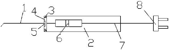
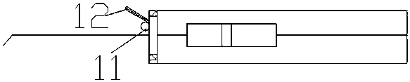
[0015] A new type of safety electric knife pen, which is provided with a knife head 1 and a knife handle 2, a knife head 1 is arranged at the front end of the knife handle 2, a sheath 3 is arranged between the knife head 1 and the knife handle 2, and the inner side of the sheath 3 is arranged There is a connection port 4, and an insertion slot 5 is arranged inside the connection port 4. The cutter head 1 is inserted into the insertion slot 5, and a control slider 6 is provided on the handle 2, and a control slider 6 is arranged on the rear end of the handle 2. There is an electric wire 7 on which a plug 8 is provided.
[0016] Described control slide block 6 is manual slide block, is provided with copper sheet on the slide block.
[0017] A copper rod 9 is arranged inside the control slider 6 , and copper sheets are arranged on both sides of the copper rod 9 .
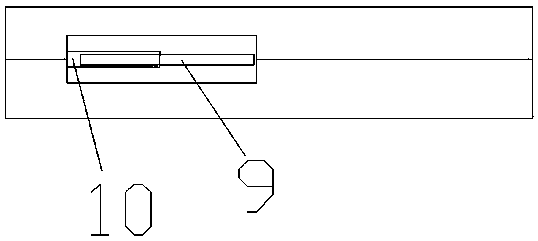
[0018] The copper rod 9 is provided with a copper sleeve 10 outside, and the copper rod 9 moves back and forth in t...
Embodiment 2
[0021] A new type of safety electric knife pen, which is provided with a knife head 1 and a knife handle 2, a knife head 1 is arranged at the front end of the knife handle 2, a sheath 3 is arranged between the knife head 1 and the knife handle 2, and the inner side of the sheath 3 is arranged There is a connection port 4, and an insertion slot 5 is arranged inside the connection port 4. The cutter head 1 is inserted into the insertion slot 5, and a control slider 6 is provided on the handle 2, and a control slider 6 is arranged on the rear end of the handle 2. There is an electric wire 7 on which a plug 8 is provided.
[0022] Described control slide block 6 is manual slide block, is provided with copper sheet on the slide block.
[0023] A copper rod 9 is arranged inside the control slider 6 , and copper sheets are arranged on both sides of the copper rod 9 .
[0024] The copper rod 9 is provided with a copper sleeve 10 outside, and the copper rod 9 moves back and forth in t...
PUM
 Abstract
Description
Claims
Application Information
 - R&D Engineer
- R&D Manager
- IP Professional
- Industry Leading Data Capabilities
- Powerful AI technology
- Patent DNA Extraction
Browse by: Latest US Patents, China's latest patents, Technical Efficacy Thesaurus, Application Domain, Technology Topic, Popular Technical Reports.
© 2024 PatSnap. All rights reserved.Legal|Privacy policy|Modern Slavery Act Transparency Statement|Sitemap|About US| Contact US: help@patsnap.com