Easy-to-adjust household antenna

An antenna and connecting shaft technology, which is applied in the field of household antennas, can solve the problems of poor control of the angle, time-consuming and labor-intensive rotation, etc., and achieve the effect of enhancing firmness and stability and high adjustment accuracy

Inactive Publication Date: 2019-06-25
万正河
View PDF3 Cites 1 Cited by
  • Summary
  • Abstract
  • Description
  • Claims
  • Application Information

AI Technical Summary

Problems solved by technology

[0004] The purpose of the present invention is to provide a household antenna that is easy to adjust, so as to solve the problem that the existing antenna can only be considered to rotate in the above background technology, the rotation is time-consuming and laborious, and the angle is not easy to control.

Method used


Image

  • Easy-to-adjust household antenna
  • Easy-to-adjust household antenna
  • Easy-to-adjust household antenna

Examples


Embodiment Construction

[0024] The following will clearly and completely describe the technical solutions in the embodiments of the present invention with reference to the accompanying drawings in the embodiments of the present invention. Obviously, the described embodiments are only some, not all, embodiments of the present invention. The specific embodiments described here are only used to explain the present invention, not to limit the present invention. Based on the embodiments of the present invention, all other embodiments obtained by persons of ordinary skill in the art without making creative efforts belong to the protection scope of the present invention.

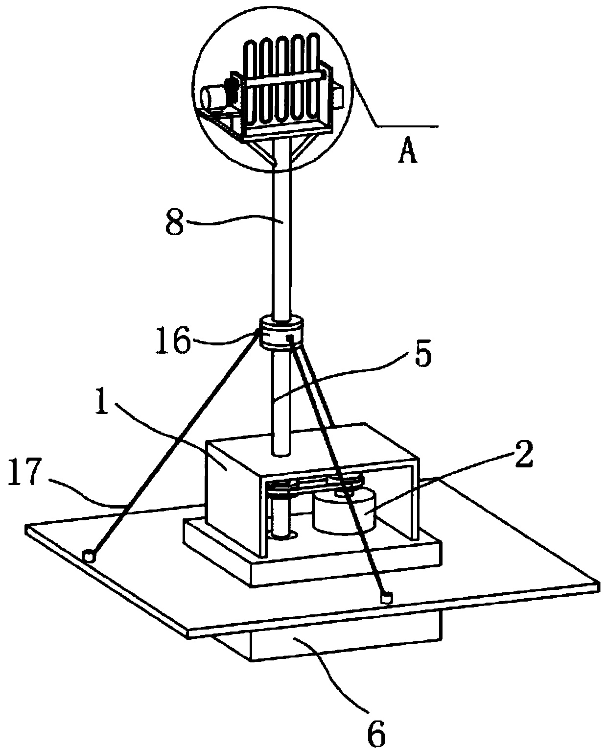
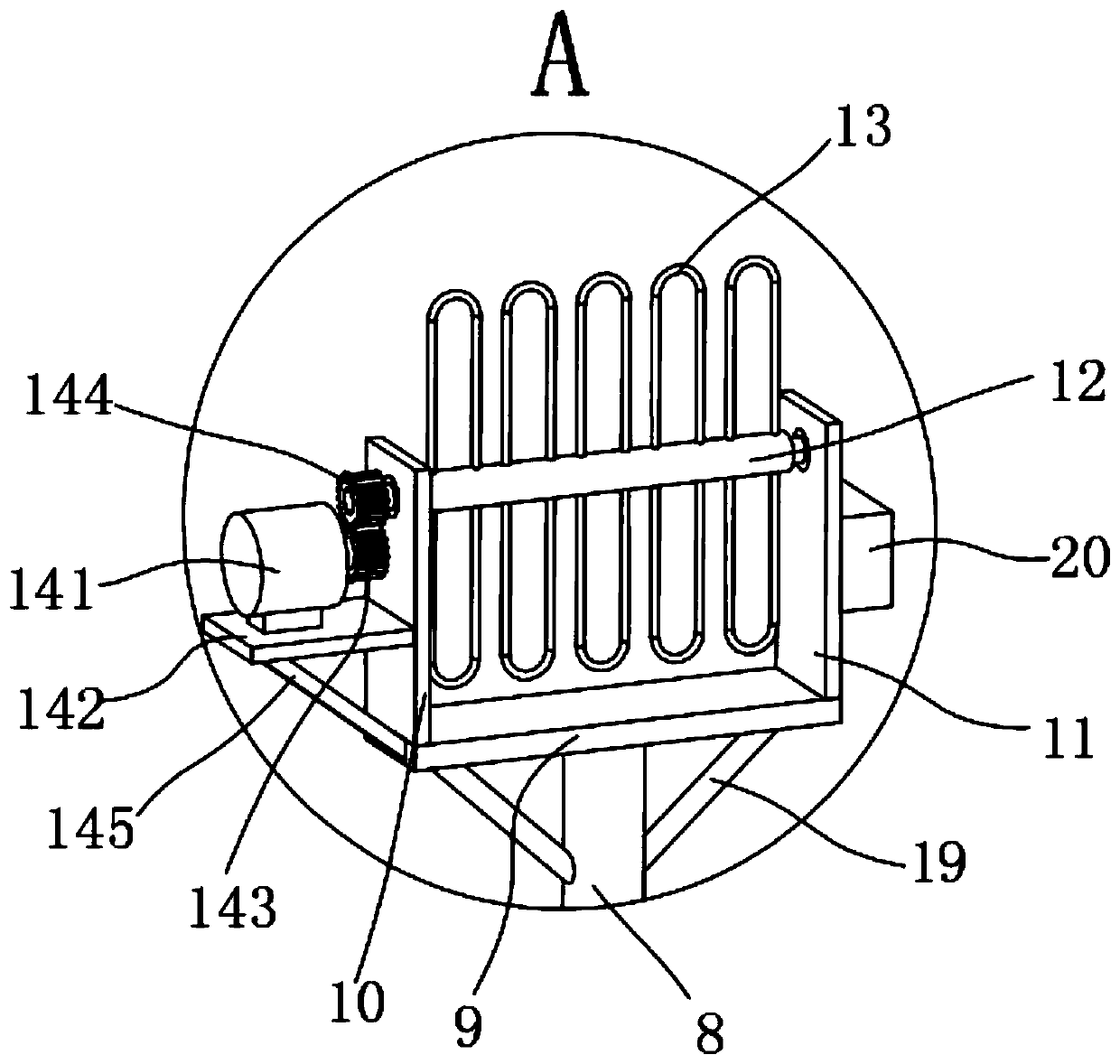
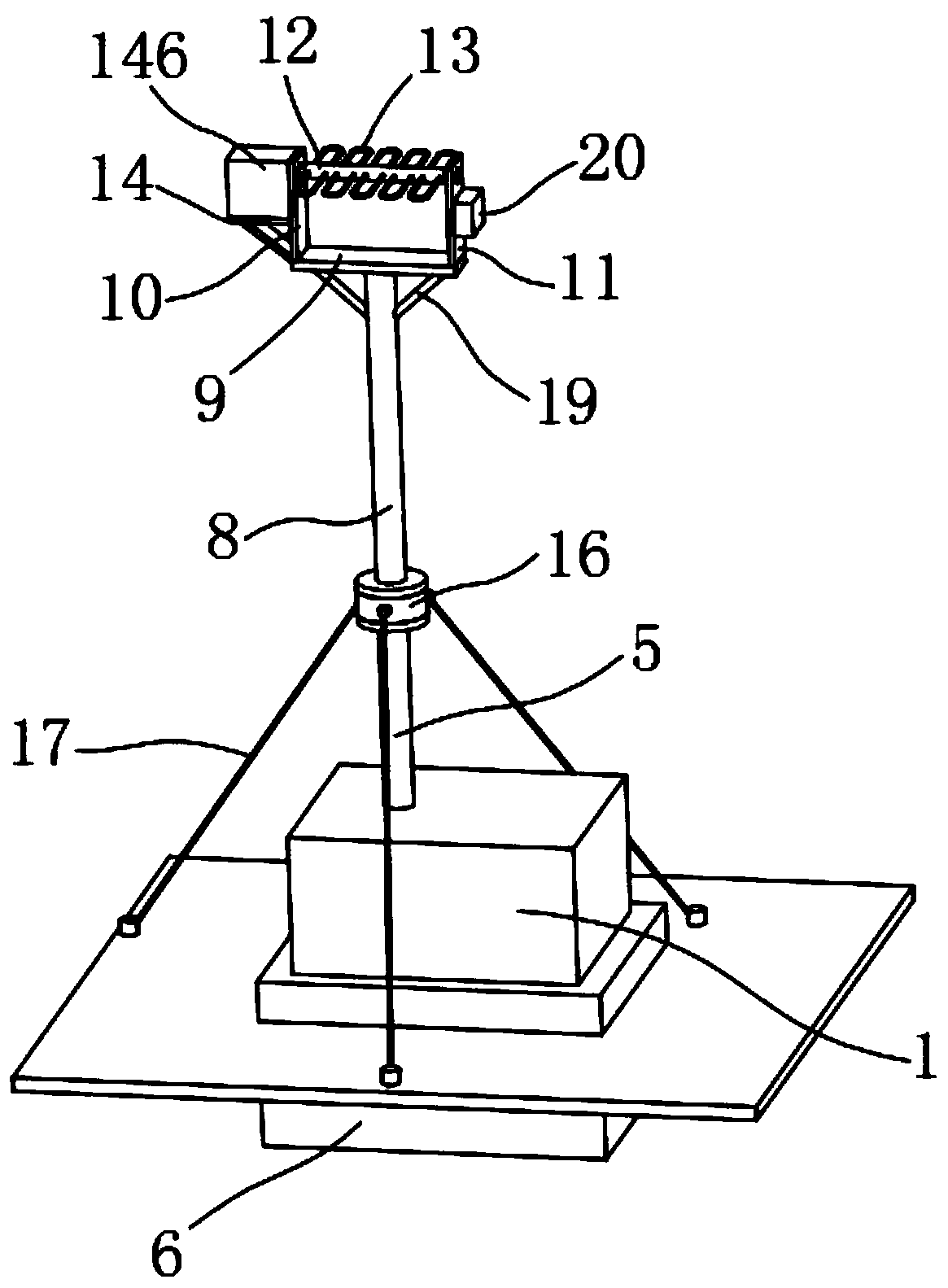
[0025] The present invention provides such Figure 1-5 The illustrated household antenna that is easy to adjust includes a box body 1, a first servo motor 2 is fixed on one side of the inner bottom end of the box body 1, and the end of the output shaft of the first servo motor 2 is fixed with a The first pulley 3, the first pulley 3 is c...


PUM


Abstract

The invention discloses an easy-to-adjust household antenna comprising a box body, wherein a first servo motor is fixed inside the box body; a first belt pulley is fixed to the output shaft of the first servo motor; the first belt pulley is in driving connection to a second belt pulley; the second belt pulley is fixed to a first support rod; a second support rod is fixed to the first support rod through a stainless steel connecting shaft; a fixing plate is fixed to the top of the second support rod; a first support plate and a second support plate are fixed to the two sides of the upper end ofthe fixing plate respectively; a connecting shaft is in rotatable connection between the first support plate and the second support plate; an antenna is fixed to the connecting shaft; and one side ofthe first support plate is provided with an angle adjustment mechanism that is connected to the connecting shaft. The antenna is automatically adjusted in the horizontal and vertical directions by means of the above structure, which avoids manual adjustment, saves time and labor, and achieves high adjustment precision.

Description

technical field [0001] The invention belongs to the technical field of household antennas, and in particular relates to a conveniently adjustable household antenna. Background technique [0002] An antenna is a transformer that transforms a guided wave propagating on a transmission line into an electromagnetic wave propagating in an unbounded medium (usually free space), or vice versa. A component used in radio equipment to transmit or receive electromagnetic waves. Engineering systems such as radio communication, broadcasting, television, radar, navigation, electronic countermeasures, remote sensing, and radio astronomy, which use electromagnetic waves to transmit information, rely on antennas to work. In addition, in terms of transmitting energy with electromagnetic waves, non-signal energy radiation also requires antennas. Generally, antennas are reversible, that is, the same antenna can be used as both a transmitting antenna and a receiving antenna. The basic characte...

Claims


Application Information

Patent Timeline
Patent Type & Authority Applications(China)
IPC IPC(8): H01Q3/02
Inventor 张芙蓉
Owner 万正河
Why Eureka
Try Eureka