Hollow shutter top operation system

An operating system and hollow technology, applied in buildings, door/window protection devices, building components, etc., can solve problems such as easy entanglement of leaf-turning ropes and lifting ropes, inability to meet indoor ventilation, and inability to open lifting windows, etc. To achieve the effect of ensuring privacy and security, saving materials and easy operation

Active Publication Date: 2019-06-21
CHANGSHU OTEK BUILDING ENERGY SAVING TECH CO LTD
View PDF5 Cites 1 Cited by
  • Summary
  • Abstract
  • Description
  • Claims
  • Application Information

AI Technical Summary

Problems solved by technology

The above two controllers placed on the same side or the built-in hollow shutters placed on the left and right sides can only be used in casement windows or translation windows, because the sliding window is composed of upper and lower built-in hollow shutters , the upper glass is a fixed glass that cannot be moved, and the lower glass is an opening fan. Lift up to open the window sash and pull down to close the window sash, so the controller is placed on the left and right sides. It will be interfered by the built-in hollow louver glass controller of the other fan (upper fixed fan) and cannot be opened. The window that cannot be opened cannot meet the requirements of indoor ventilation.
The reason why the sliding window cannot be opened is because the built-in hollow louver glass flipping and lifting controller protrusion is at the same height as the opening fan, thus hindering the lifting type opening
[0003] In addition, the common built-in hollow louver glass flipping and lifting controllers are on the same side, and the flipping rope of the internal flipping mechanism and the lifting rope of the lifting mechanism are controlled in the same chute, and the flipping rope and the lifting rope are easily entangled in the same chute together cause a sliding failure

Method used


Image

  • Hollow shutter top operation system
  • Hollow shutter top operation system
  • Hollow shutter top operation system

Examples


Embodiment Construction

[0019] In the following description, for purposes of explanation, numerous specific details are set forth in order to provide a thorough understanding of one or more embodiments. It may be evident, however, that these embodiments may be practiced without these specific details. In other instances, well-known structures and devices are shown in block diagram form in order to facilitate describing one or more embodiments.

[0020] Various embodiments according to the present invention will be described in detail below with reference to the accompanying drawings.

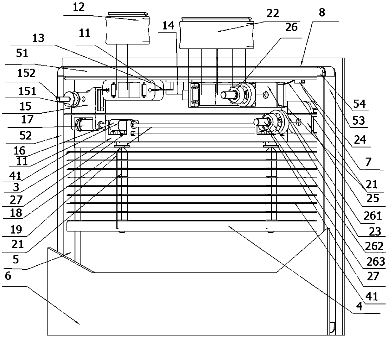
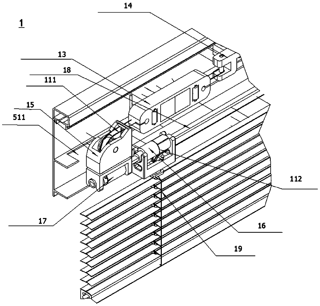
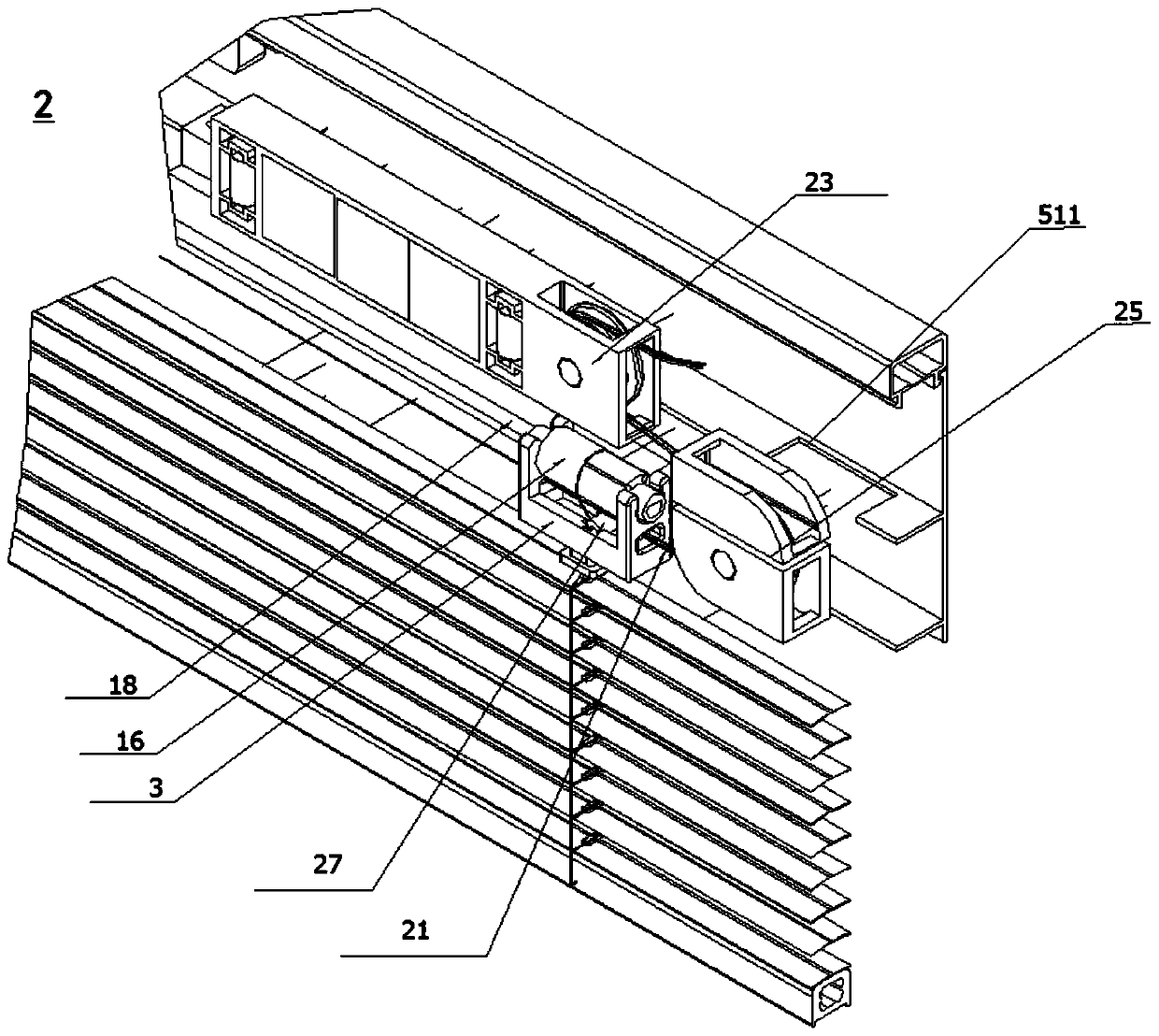
[0021] figure 1 It is a schematic diagram of the operating system at the top of the hollow louver according to the present invention, such as figure 1 As shown, the hollow louver top operating system includes a turning mechanism 1 and a lifting mechanism 2, the turning mechanism 1 is used for the opening and closing of the louvers 41 of the venetian blind 4, and the lifting mechanism 2 is used for lifting the venetia...


PUM


Abstract

The invention provides a hollow shutter top operation system, comprising a turnover mechanism and a lifting mechanism, and the turnover mechanism is used for opening and closing louver blades of a louver curtain; the lifting mechanism is used for lifting the louver curtain; the turnover mechanism comprises a turnover rope and a top turnover control piece; the turnover rope is connected to the topturnover control piece from one side of the louver curtain; the lifting mechanism comprises a lifting rope and a top lifting control piece, the lifting rope is connected to the top lifting control piece from the other side of the louver curtain, the louver curtain is located in a window frame, and the top turnover control piece and the top lifting control piece are arranged on the window frame onthe upper side of the louver curtain. The turnover rope and the lifting rope of the hollow shutter top operation system are not entangled.

Description

technical field [0001] The invention relates to the technical field of hollow louvered glass windows, in particular to a hollow louver top operating system. Background technique [0002] Built-in hollow louver glass has been widely used all over the world due to its good heat insulation, sound insulation, anti-condensation, anti-dust pollution, beautiful appearance and other advantages. The controller is placed on the same side or the flip and lift controllers are placed separately on the left and right sides to control the flip and lift functions of the venetian blinds. The above two controllers placed on the same side or the built-in hollow shutters placed on the left and right sides can only be used in casement windows or translation windows, because the sliding window is composed of upper and lower built-in hollow shutters , the upper glass is a fixed glass that cannot be moved, and the lower glass is an opening fan. Lift up to open the window sash and pull down to clos...

Claims


Application Information

Patent Timeline
Patent Type & Authority Applications(China)
IPC IPC(8): E06B9/322E06B9/264
CPCE06B9/264E06B2009/2646E06B9/308E06B9/322E06B2009/3222E06B9/326
Inventor 金承哲金仁哲安相俊
Owner CHANGSHU OTEK BUILDING ENERGY SAVING TECH CO LTD
Why Eureka
Try Eureka