Laser radar detection device and method for short-distance barriers

A detection device and obstacle detection technology, applied in the field of obstacle detection, can solve the problems of limited number of obstacles, limited FOV, and inability to apply close-range detection

Pending Publication Date: 2019-06-18
AUTOMOTIVE RES & TESTING CENT
View PDF15 Cites 9 Cited by
  • Summary
  • Abstract
  • Description
  • Claims
  • Application Information

AI Technical Summary

Problems solved by technology

For example, the 77G Hz radar is responsible for long-distance detection, the field of view (Field Of View, FOV) is 34 degrees, and the blind area is within 2 meters. Limited, it is difficult to accurately model obstacles
The camera is responsible for long-distance detection, the FOV is 90 degrees, and the blind spot is within 10 meters. It can detect the position 80 meters away from the camera, but it is easily affected by heavy rain, dense fog, strong light and weather
The 24G Hz radar is responsible for mid-range detection. The FOV is 80 degrees. It can detect the position 40 meters away from the 24G Hz radar, but it cannot capture the obstacles on the side (B-pillar) of the car body, and the detected obstacles The number is limited, the data error is large, etc.
To sum up the above, at present, radars and cameras are commonly used in self-driving cars. However, due to their respective disadvantages such as high noise, being easily affected by environmental factors, and being unable to be used for short-range detection, 3D lidars with high reliability are gradually becoming popular. However, the data volume of 3D LiDAR is huge, and a high-efficiency platform is required to process the corresponding data volume. Moreover, at present, a variety of sensors are generally used to complement each other in order to complement each other, resulting in relatively high overall cost. expensive

Method used


Image

  • Laser radar detection device and method for short-distance barriers
  • Laser radar detection device and method for short-distance barriers
  • Laser radar detection device and method for short-distance barriers

Examples


Embodiment Construction

[0018] Embodiments of the present invention will be further explained with the help of related figures below. Wherever possible, the same reference numerals have been used in the drawings and description to refer to the same or similar components. In the drawings, the shape and thickness may be exaggerated for the sake of simplification and convenient labeling. It can be understood that components not particularly shown in the drawings or described in the specification are forms known to those skilled in the art. Those skilled in the art can make various changes and modifications according to the content of the present invention.

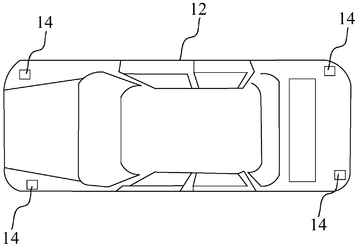
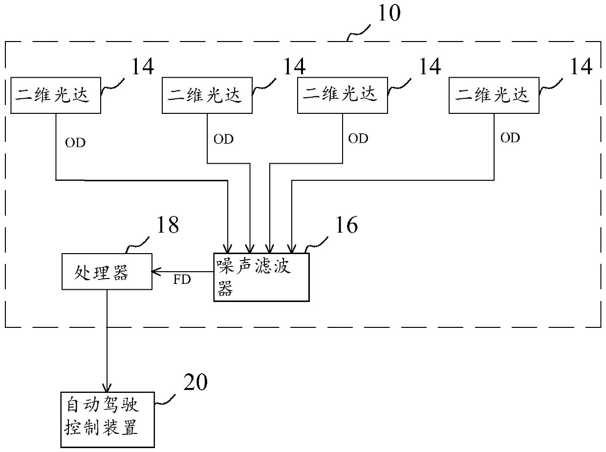
[0019] see below figure 1 , figure 2 and image 3 . The following describes the LiDAR detection device 10 for short-distance obstacles of the present invention, which is installed in a vehicle 12. There is at least one obstacle around the vehicle 12, and the number of obstacles is taken as an example. The distance between each obstacle and th...


PUM


Abstract

The invention discloses a laser radar detection device and method for short-distance barriers. According to the invention, four two-dimensional laser radars are utilized to scan the barriers so as toobtain original point cloud data corresponding to the barriers, wherein the original point cloud data comprises relative distances, relative angles and relative speeds of the barriers relative to a vehicle; then the point cloud data is partitioned into point cloud groups of the corresponding barriers, and according to outlines of the point cloud groups, boundary lengths of the barriers are obtained; and finally, motion paths of the dynamic barriers are predicted and tracked by utilizing a Kalman filtering method and an extrapolation method, the relative speeds and the boundary lengths of the corresponding dynamic barriers are transmitted to an automatic driving control device for use, then according to the relative distances, coordinates of the dynamic barrier which is the closest to the vehicle are obtained, and the coordinates are transmitted to the automatic driving control device for use so as to effective detect the barriers.

Description

technical field [0001] The present invention relates to an obstacle detection technology, and in particular to a lidar detection device and method for short-distance obstacles. Background technique [0002] An autonomous vehicle is an intelligent vehicle that senses the road environment through a sensing system, and uses the road, vehicle position and obstacle information obtained from the sensing to control the driving parameters of the vehicle, thereby enabling the vehicle to travel safely and reliably on the road. Drive and reach the intended destination. Self-driving vehicles employ computing, sensing, communication, information fusion, artificial intelligence and automatic control technologies, and have become the research focus of countries all over the world. [0003] Environmental sensors are an indispensable component of autonomous vehicles, including 77 gigahertz (G Hz) radar, cameras, 24 gigahertz (G Hz) radar and three-dimensional Lidar, two-dimensional Lidar ,...

Claims


Application Information

Patent Timeline
Patent Type & Authority Applications(China)
IPC IPC(8): G01S17/93
Inventor 萧翔民陈盈仁许立佑
Owner AUTOMOTIVE RES & TESTING CENT
Why Eureka
Try Eureka