
Method, system and active sound device for optimizing acoustic environment in vehicle

An acoustic environment and internal sound technology, applied in the field of active sound equipment and optimizing the acoustic environment in the car, can solve problems such as confusion of forward and reverse gears, affecting the user's driving experience, and weak subjective driving experience, so as to improve the driving experience Experience and improve the effect of weaker subjective feelings and enhance the overall driving experience

Active Publication Date: 2020-12-25
BYD CO LTD
View PDF6 Cites 0 Cited by
  • Summary
  • Abstract
  • Description
  • Claims
  • Application Information

AI Technical Summary

Problems solved by technology

Most of the existing noise reduction technologies include sound signal detection, noise extraction, analysis, and noise cancellation. Among them, the steps of noise cancellation are usually more complicated. For example, complex adaptive LMS filters are usually used to process noise signals. deal with
[0003] In addition, as the operation of in-vehicle equipment tends to be electronic, one of the disadvantages is that the user's subjective experience of driving is weak. Users easily confuse forward and reverse gears, etc., which greatly affects the user's driving experience
As for how to improve the problem of poor driving experience caused by equipment operation tending to be electronic, the prior art has not yet proposed a better solution.

Method used


Image

  • Method, system and active sound device for optimizing acoustic environment in vehicle
  • Method, system and active sound device for optimizing acoustic environment in vehicle
  • Method, system and active sound device for optimizing acoustic environment in vehicle

Examples


Embodiment Construction

[0048] In order to make the technical problems, technical solutions and beneficial effects to be solved by the present invention clearer, the present invention will be further described in detail below in conjunction with the accompanying drawings and embodiments. It should be understood that the specific embodiments described here are only used to explain the present invention, not to limit the present invention.

[0049] It should be noted that when an element is referred to as being “fixed” or “disposed on” another element, it may be directly on the other element or there may be an intervening element at the same time. When an element is referred to as being "connected to" another element, it can be directly connected to the other element or intervening elements may also be present.

[0050] In the description of the present invention, it should be understood that the terms "first" and "second" are used for description purposes only, and cannot be interpreted as indicating ...


PUM


Abstract

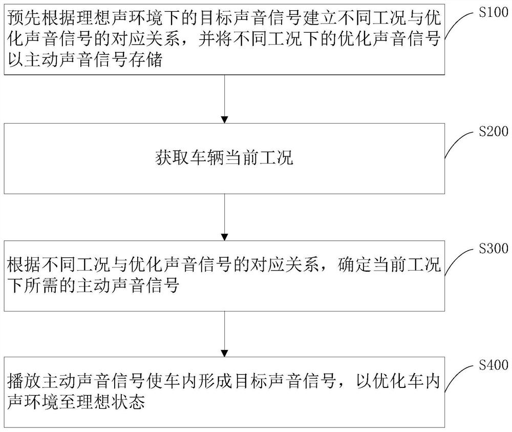
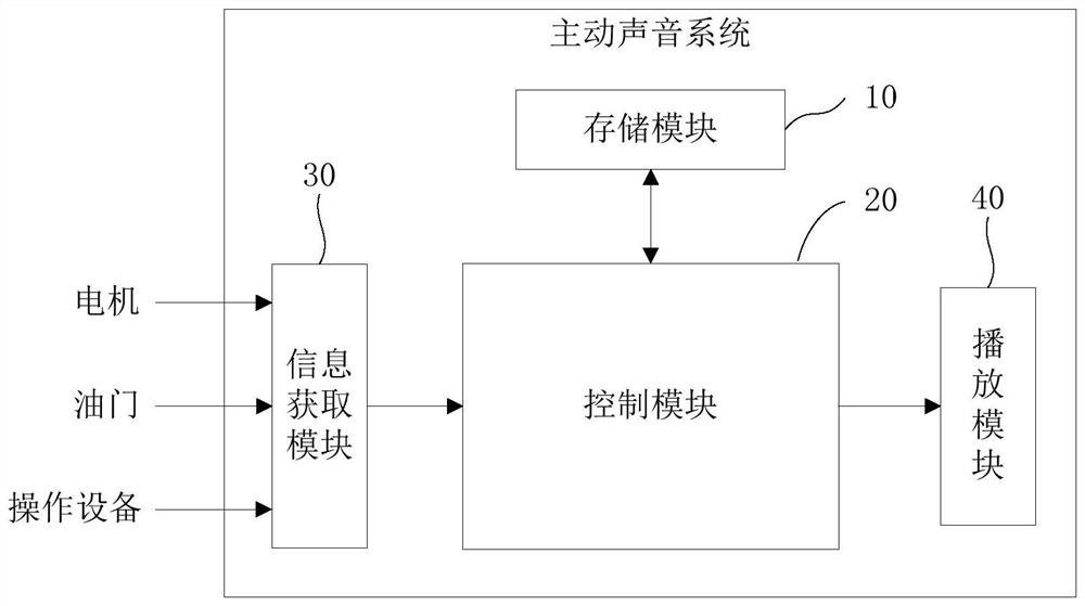
The invention discloses a method for optimizing a sound environment in a vehicle, which comprises the following steps of: establishing corresponding relations between different working conditions andoptimized sound signals in advance according to target sound signals in an ideal sound environment, and storing the optimized sound signals in different working conditions as active sound signals; obtaining the current working condition of the vehicle; determining an active sound signal required under the current working condition according to the corresponding relationships between the differentworking conditions and the optimized sound signals; and playing the active sound signal to form the target sound signal in the vehicle so as to optimize the sound environment in the vehicle to an ideal state. The method is simple and practical, not only is beneficial to timely playing of the active sound signal to obtain an ideal in-vehicle sound environment, but also can achieve the purpose of carrying out sound prompting according to different working conditions, overcomes the defect that subjective feelings of a user on the working condition of the vehicle are weak due to the fact that equipment operation tends to be electronized, and improves overall driving and riding experience of the user. The invention further provides a system for optimizing the in-vehicle sound environment and active sound equipment.

Description

technical field [0001] The present invention relates to a technology for optimizing the acoustic environment inside a vehicle, in particular to a method, a system and an active sound device for optimizing the acoustic environment inside a vehicle, which are especially suitable for new energy vehicles. Background technique [0002] At present, in order to optimize the acoustic environment inside the vehicle, the research directions proposed in the prior art mainly involve noise reduction technology. Most of the existing noise reduction technologies include sound signal detection, noise extraction, analysis, and noise cancellation. Among them, the steps of noise cancellation are usually more complicated. For example, complex adaptive LMS filters are usually used to process noise signals. deal with. [0003] In addition, as the operation of in-vehicle equipment tends to be electronic, one of the disadvantages is that the user's subjective experience of driving is weak. Users ...

Claims


Application Information

Patent Timeline
Patent Type & Authority Patents(China)
IPC IPC(8): H04R3/12
Inventor 孙亚轩赵永吉
Owner BYD CO LTD
Learn More