A Method for Realizing Vertical Take-off and Landing and Horizontal Flight with Segmented Bottom Drive Type Wing

A vertical take-off and landing, plate-wing technology, applied to vertical take-off and landing aircraft, aircraft, transportation and packaging, etc., can solve the problems of not smooth and natural vertical take-off and landing mode conversion, divergence of chord blowing airflow, and insufficient vertical lift. To achieve the effects of no sudden change in the control effect, smooth changes in control parameters, and improved flight efficiency

Active Publication Date: 2021-02-05
KUNMING QIAOYI SCI & TECH CO LTD
View PDF8 Cites 0 Cited by
  • Summary
  • Abstract
  • Description
  • Claims
  • Application Information

AI Technical Summary

Problems solved by technology

[0005] The technical problem to be solved by the present invention is that the flight efficiency of the existing vertical take-off and landing aircraft is low, the thrust-to-weight ratio is small, the control is complicated, the safety is poor, the conversion between the horizontal flight mode and the vertical take-off and landing mode is not smooth and natural, and the wings of the existing plank wing To deal with problems such as excessive resistance, insufficient vertical lift, and divergence of the chord-wise blowing airflow, a method of using a segmented bottom-driven plate wing to achieve vertical take-off and landing and horizontal flight is proposed. The plate wing is divided into multiple sections to open the air intake channel and enhance the vertical The lift of take-off and landing takes into account the horizontal flight. After the movable strip-shaped wing rotates to open the intake channel to increase the lift to realize vertical take-off and landing, the movable strip-shaped wing can be rotated and closed, and it can be closed with the fixed strip-shaped wing to form a whole. plate wing, so as to reduce resistance and achieve high-speed flight, making the plate wing aircraft safer, more efficient, compact, stable and reasonable

Method used


Image

  • A Method for Realizing Vertical Take-off and Landing and Horizontal Flight with Segmented Bottom Drive Type Wing
  • A Method for Realizing Vertical Take-off and Landing and Horizontal Flight with Segmented Bottom Drive Type Wing
  • A Method for Realizing Vertical Take-off and Landing and Horizontal Flight with Segmented Bottom Drive Type Wing

Examples


Embodiment 1

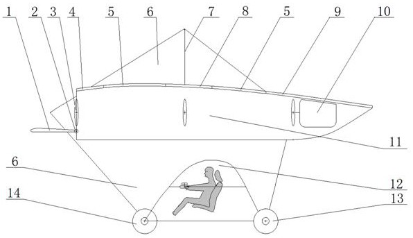
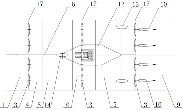
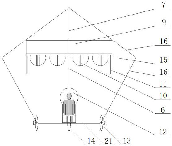
[0040] Embodiment 1: as Figure 1-19 Shown, the method that the present invention realizes vertical take-off and landing and horizontal flight with segmented bottom drive type plate wing is: adopt the sheet fuselage (the height-to-width ratio of fuselage is 5) aircraft of large-area plate-shaped wing for wing , the large-area plate-shaped wing is designed as a combined type, and it is divided into three sections of movable strip-shaped wings and two sections of fixed strip-shaped wings along the transverse direction. The movable strip-shaped wings and fixed strip-shaped wings are arranged alternately like zebra crossings. Through the tilting of the movable strip-shaped wing, the movable strip-shaped wing and the fixed strip-shaped wing can be combined into an integral plate-shaped wing to adapt to horizontal flight, and the movable strip-shaped wing can be opened laterally like a shutter A strip-shaped air intake hole is formed to realize vertical take-off and landing; a secti...

Embodiment 2

[0047] Embodiment 2: as Figure 1-19 As shown, the method for realizing vertical take-off and landing and horizontal flight of the present invention with segmented bottom-driven plate wings is the same as that of Embodiment 1. The wings of the aircraft adopt large-area combined plate-shaped wings, and the fuselage adopts an aspect ratio of 6. sheet body. The large-area plate-shaped wing is divided into 5 sections of movable strip-shaped wings and 4 sections of fixed strip-shaped wings along the transverse direction, and 3 sections of activities are set between the frontmost movable strip-shaped wing and the rearmost movable strip-shaped wing. The strip-shaped wing and 4 fixed strip-shaped wings, the bottom of each movable strip-shaped wing is fixed side by side with a group of jet engine driving devices, the distance between two adjacent groups of driving devices (that is, two adjacent The distance between the movable strip-shaped wings) is greater than 6 times the diameter D...

Embodiment 3

[0048] Embodiment 3: as Figure 1-19 As shown, the method for realizing vertical take-off and landing and horizontal flight of the present invention with segmented bottom-driven plate wings is the same as that of embodiment 1. The wings of the aircraft adopt large-area combined plate-shaped wings, and the fuselage adopts an aspect ratio of 4. sheet body. The large-area plate-shaped wing is divided into 8 sections of movable strip-shaped wings and 7 sections of fixed strip-shaped wings along the transverse direction, and 6 sections of activities are set between the frontmost movable strip-shaped wing and the rearmost movable strip-shaped wing. Strip-shaped wings and 7 sections of fixed strip-shaped wings, a group of 10 propeller drive devices are fixed side by side under each movable strip-shaped wing, and the distance between two adjacent sets of drive devices (that is, two adjacent movable The distance between the strip-shaped wings) is greater than 10 times the diameter D o...


PUM


Abstract

The invention discloses a method for realizing vertical take-off and landing and horizontal flight by using segmented bottom-driven plate wings, which belongs to the field of aviation technology. The large-area plate-shaped wing is divided horizontally into several sections of movable strip-shaped wing and fixed strip-shaped wing. The fixed strip-shaped wing is rigidly connected to the fuselage without moving parts. The movable strip-shaped wing and the fuselage are connected through a transverse hinge. Connected and can be tilted longitudinally; the lower part of the movable strip-shaped wing is fixedly connected with the driving device, and tilts like a shutter. When it is turned horizontal, it is combined into a large-area plate-shaped wing. The high-speed airflow is blown along the chord direction to realize horizontal flight, and the strip-shaped air intake hole is opened when it is turned vertically. Different requirements for flight and vertical take-off and landing, improve vertical take-off and landing capability and flight efficiency, realize smooth switching of flight modes, stable work, intuitive operation, safe and reliable, and easy to operate.

Description

technical field [0001] The invention relates to a method for realizing vertical take-off and landing and flight of an aircraft, especially a method for installing a driving mechanism under a plate wing and dividing the plate wing into multiple sections so as to open the air intake channel to enhance the lift force of the vertical take-off and landing and take into account the horizontal flight method , belonging to the field of aviation technology. Background technique [0002] Manned aircraft can be divided into two categories: fixed wing and rotary wing. Fixed wing is commonly used in horizontal take-off and landing aircraft (such as jet airliners), while rotary wing is commonly used in vertical take-off and landing aircraft (such as helicopters). As far as the current technical level is concerned, fixed-wing aircraft can fly at high speed and are easy to operate, but they need to rely on runways to take off and land. Rotary wing aircraft can take off and land vertically ...

Claims


Application Information

Patent Timeline
Patent Type & Authority Patents(China)
IPC IPC(8): B64C29/00
Inventor 杨卫华
Owner KUNMING QIAOYI SCI & TECH CO LTD
Why Eureka
Try Eureka