
A composite material wing positioning structure assembly and demoulding integrated tooling and using method thereof

A positioning structure and composite material technology, applied in the field of composite material molding, can solve the problems of scratching the joint shaft hole matching shaft hole, the mold shaft hole affecting the positioning shaft assembly and disassembly process, and it is difficult to ensure the vertical angle of the positioning shaft. The operability and promotion and application value, the effect of solving the damage and reducing the risk

Active Publication Date: 2021-04-30
AEROSPACE INST OF ADVANCED MATERIALS & PROCESSING TECH
View PDF6 Cites 0 Cited by
  • Summary
  • Abstract
  • Description
  • Claims
  • Application Information

AI Technical Summary

Problems solved by technology

In the previous wing forming process, the positioning shaft was manually installed and disassembled in the forming tool by the operator, and the uniformity of the matching gap between the positioning shaft and the joint shaft hole was completely observed by the naked eye. vertical angle of
When the positioning shaft and the normal direction of the joint shaft hole are at a certain angle, the sharp part of the edge may scratch the joint shaft hole and the matching shaft hole of the bottom mold and the upper mold of the forming tooling, and the burr of the mold shaft hole will further affect the positioning Shaft assembly and disassembly process, resulting in a vicious circle

Method used


Image

  • A composite material wing positioning structure assembly and demoulding integrated tooling and using method thereof
  • A composite material wing positioning structure assembly and demoulding integrated tooling and using method thereof

Examples


Embodiment Construction

[0044] In order to make the purpose, technical solutions and advantages of the embodiments of the present invention clearer, the technical solutions in the embodiments of the present invention will be clearly and completely described below in conjunction with the drawings in the embodiments of the present invention. Obviously, the described embodiments It is a part of embodiments of the present invention, but not all embodiments. Based on the embodiments of the present invention, all other embodiments obtained by persons of ordinary skill in the art without making creative efforts belong to the protection scope of the present invention.

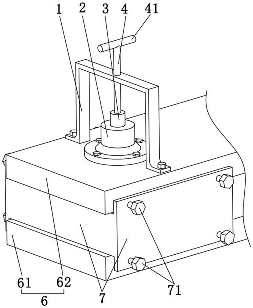
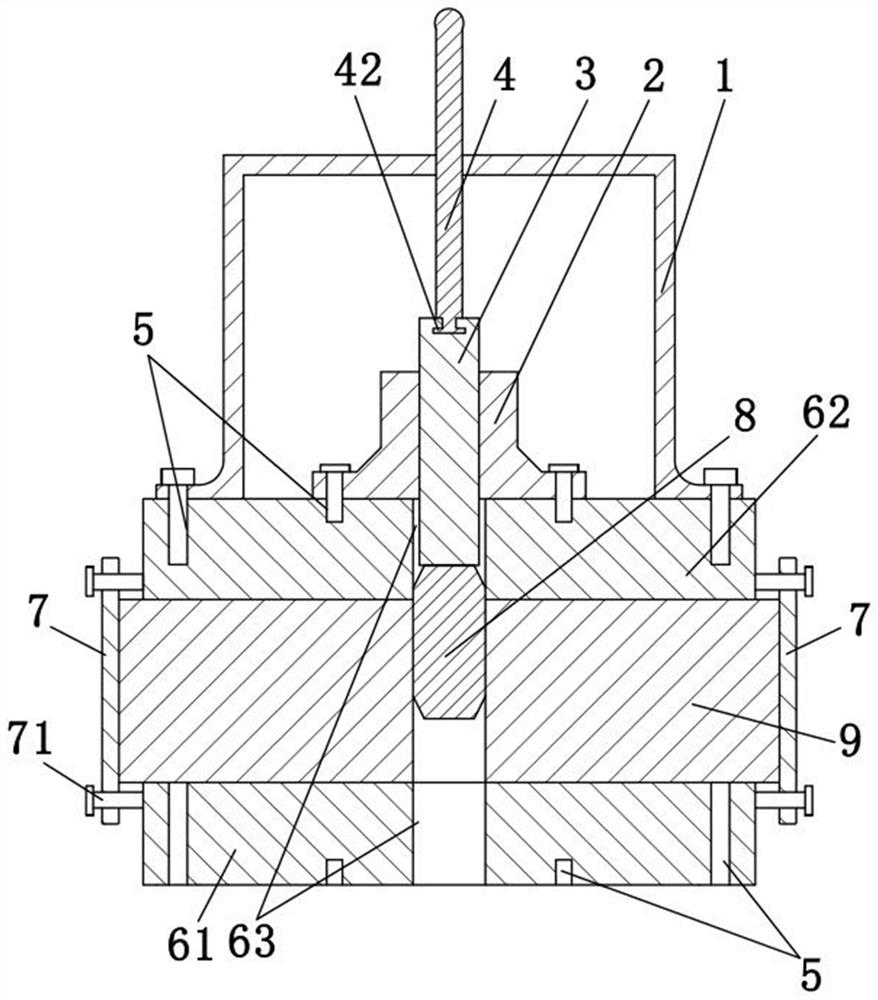
[0045] A composite material wing positioning structure assembly and demoulding integrated tooling and its use method, combined with figure 1 , figure 2 , including support 1, flange 2, pressure block 3 and lead screw 4, support 1 is a door-shaped steel frame, lead screw 4 is threaded in the middle of the top of support 1, and the length dir...


PUM


Abstract

The invention relates to a composite material wing positioning structure assembly and demoulding integrated tooling and its use method, comprising a support, a flange, a pressure block and a lead screw, the lead screw is threaded on the support, and the pressure block is erected on the wire At one end of the bar, the pressure block is slidably connected in the flange, wherein the wing is erected in the mould, the support and the flange are fixedly connected to the end surface of the mould, and the mold is slidably connected with a positioning shaft, and the pressure block is in contact with the positioning shaft. Then, the lead screw rotates so that the pressure block pushes the positioning shaft into the wing or pushes it out of the wing. The invention can ensure the direction and angle of the positioning shaft movement, and ensure the uniform clearance between the positioning shaft and the joint shaft hole during the movement process. It has the advantages of solving the problem of damage to the shaft hole of the metal joint of the composite wing and reducing the risk of aircraft deployment tests and flight tests.

Description

technical field [0001] The invention relates to the technical field of composite material forming, and in particular to a composite material wing positioning structure assembly and release integrated tooling and a use method thereof. Background technique [0002] The composite materialization of the fuselage structure can greatly reduce the weight, increase the fuel capacity of the aircraft, and effectively improve the range and fuel economy performance. It has become the development direction of advanced structural materials for aerospace. [0003] Foreign countries often regard the application ratio of composite materials as an important criterion for measuring the development level of aircraft. In the domestic aerospace field, composite wings tend to gradually replace metal wings in the overall structure of aircraft. [0004] A certain type of wing is almost entirely made of composite materials, and there is only a metal joint at the connection between the wing and the fu...

Claims


Application Information

Patent Timeline
Patent Type & Authority Patents(China)
IPC IPC(8): B29C33/30B29C33/44
Inventor 韩蕾卢山王国勇龚文化汪东
Owner AEROSPACE INST OF ADVANCED MATERIALS & PROCESSING TECH
Learn More