An anti-vibration cable tray

A technology of cable tray and side plate, applied in electrical components and other directions, can solve problems such as poor shock resistance

Active Publication Date: 2020-10-20
皖缆集团股份有限公司
View PDF7 Cites 0 Cited by
  • Summary
  • Abstract
  • Description
  • Claims
  • Application Information

AI Technical Summary

Problems solved by technology

[0005] Aiming at the deficiencies of the prior art, the present invention provides an anti-shock cable bridge, which solves the problem of poor shock resistance of the traditional bridge

Method used


Image

  • An anti-vibration cable tray
  • An anti-vibration cable tray
  • An anti-vibration cable tray

Examples


Embodiment Construction

[0027] The following will clearly and completely describe the technical solutions in the embodiments of the present invention with reference to the accompanying drawings in the embodiments of the present invention. Obviously, the described embodiments are only some, not all, embodiments of the present invention. Based on the embodiments of the present invention, all other embodiments obtained by persons of ordinary skill in the art without making creative efforts belong to the protection scope of the present invention.

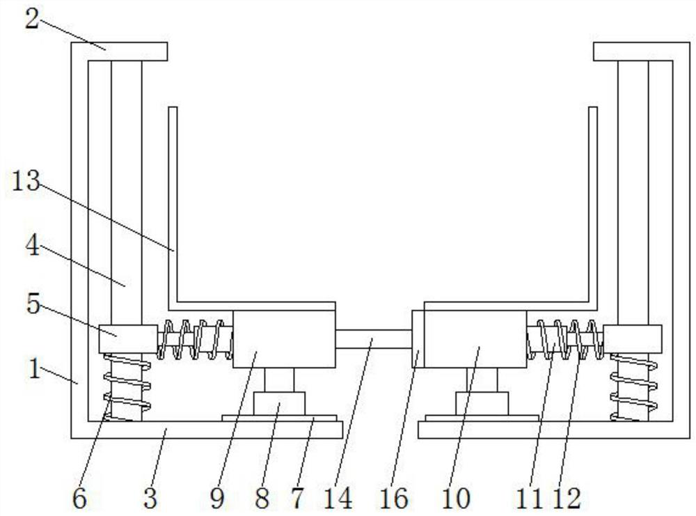
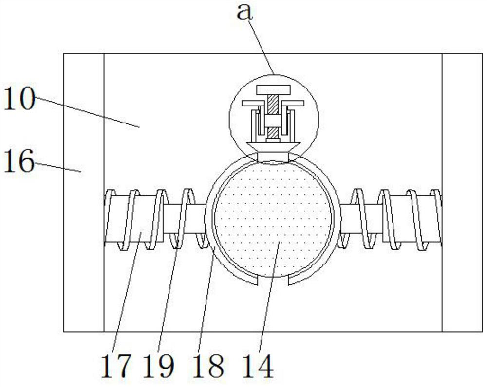
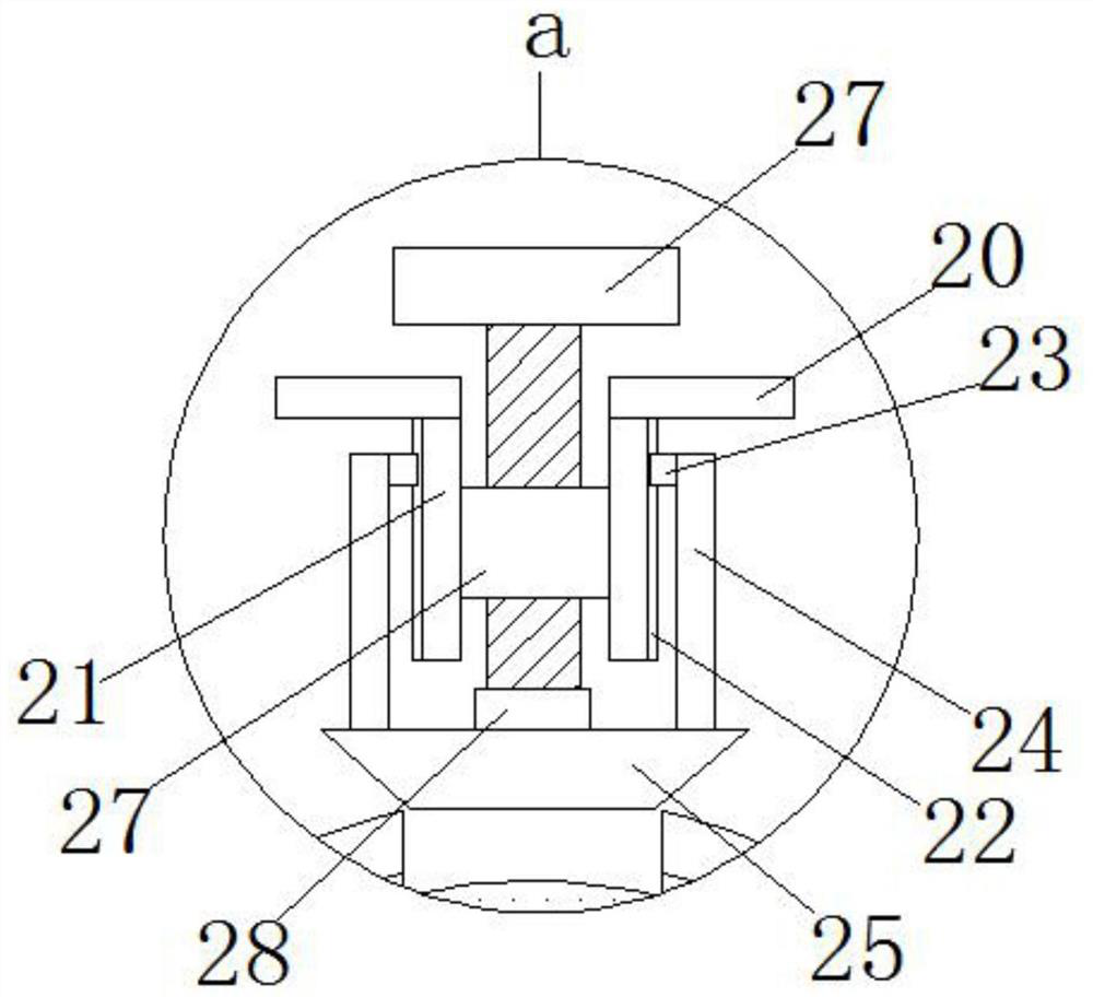
[0028] Such as Figure 1-5 As shown, the present invention provides a technical solution: a shockproof cable tray, including two symmetrical side plates 1, and the sides of the side plates 1 are provided with evenly distributed ventilation holes 29 to provide heat dissipation for the cables and avoid damage caused by the cables. When the temperature is too high during work and an accident occurs, the top and bottom of the side plate 1 are respectively provided...


PUM


Abstract

The invention relates to the technical field of cable bridges, and discloses a shock-proof cable bridge. The shock-proof cable bridge comprises two symmetrical side plates, the tops and bottoms of theside plates are provided with upper flangings and lower flangings correspondingly, sliding rods are fixedly mounted between the near side surfaces of the upper flangings and the lower flangings, slide sleeves are movably connected to the outer surfaces of the sliding rods, and first springs are fixedly mounted between the bottoms of the sliding sleeves and the upper surfaces of the lower flangings. First slide rails are fixedly mounted on the upper surfaces of the lower flangings, first telescopic rods are movably connected to the upper surfaces of the first slide rails, and a fixed plate anda mounting plate are separately and fixedly mounted on the upper surfaces of the two telescopic rods. Cable placement seats are fixedly mounted on the upper surfaces of the fixed plate and the mounting plate, a connecting rod is fixedly mounted on the right side surface of the fixed plate, and a groove is formed in the left side surface of the mounting plate. The shock-proof cable bridge increases the shock-proof performance of the cable bridge, and the phenomenon that the bridge is subjected to pressure and the connecting rod is broken is avoided.

Description

technical field [0001] The invention relates to the technical field of cable bridges, in particular to an anti-shock cable bridge. Background technique [0002] Cable trays are divided into trough type, tray type, ladder type, grid type and other structures, and are composed of brackets, supporting arms and installation accessories. It can be erected independently, or it can be laid on the supports of various buildings and pipe corridors. It embodies the characteristics of simple structure, beautiful appearance, flexible configuration and convenient maintenance. All parts need to be galvanized and installed on the bridge outside the building , if it is near the seaside or in a corrosion area, the material must have the physical characteristics of anti-corrosion, moisture resistance, good adhesion, and high impact resistance. [0003] The bridge is a cable support that needs to be used in electric power. The existing bridge has poor shockproof effect during use, so the pract...

Claims


Application Information

Patent Timeline
Patent Type & Authority Patents(China)
IPC IPC(8): H02G3/04
Inventor 丁义明
Owner 皖缆集团股份有限公司
Why Eureka
Try Eureka