
A bionic centrifugal pump blade

A centrifugal pump and blade technology, which is applied in the field of energy saving and emission reduction, can solve the problems of complicated design process of cylindrical blades and difficulty in applying twisted blades, and achieves the effects of small modeling area, reduction of processing volume, and improvement of work efficiency.

Active Publication Date: 2021-01-15
JIANGSU UNIV
View PDF7 Cites 0 Cited by
  • Summary
  • Abstract
  • Description
  • Claims
  • Application Information

AI Technical Summary

Problems solved by technology

However, this design complicates the simple cylindrical blade design process and is difficult to apply to twisted blades

Method used


Image

  • A bionic centrifugal pump blade
  • A bionic centrifugal pump blade
  • A bionic centrifugal pump blade

Examples


Embodiment Construction

[0022] Embodiments of the present invention are described in detail below, examples of which are shown in the drawings, wherein the same or similar reference numerals designate the same or similar elements or elements having the same or similar functions throughout. The embodiments described below by referring to the figures are exemplary and are intended to explain the present invention and should not be construed as limiting the present invention.

[0023] In describing the present invention, it is to be understood that the terms "central", "longitudinal", "transverse", "length", "width", "thickness", "upper", "lower", "axial", The orientation or positional relationship indicated by "radial", "vertical", "horizontal", "inner", "outer", etc. is based on the orientation or positional relationship shown in the drawings, and is only for the convenience of describing the present invention and simplifying the description , rather than indicating or implying that the device or elem...


PUM


Abstract

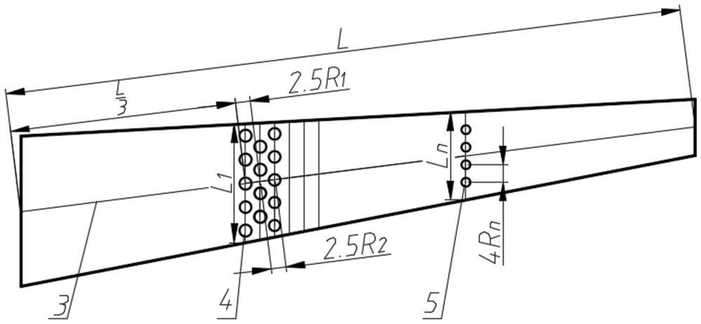
The invention provides a bionic centrifugal pump blade. A bionic structure is arranged on the back side of the blade and comprises a plurality of lines of spherical pits. Each line of spherical pits are arranged in the width direction of the blade. The start position of the bionic structure is arranged at the position 1 / 3L away from the inlet edge of the blade, wherein L is the length of the blade. When the bionic centrifugal pump blade works, low-speed fluid forms vortexes, and the vortexes accumulate in the spherical pits. The bionic centrifugal pump blade lowers the corresponding flow losscaused by wall shear stress, improves the work efficiency of an impeller and prolongs the service life of the blade. Meanwhile, it is only needed to arrange the bionic structure in the middle of the back face of the blade, the shaping area of the bionic structure is small, so that the machining amount is reduced, machining is facilitated, and cost is lowered.

Description

technical field [0001] The invention relates to blade modeling technology in the field of energy saving and emission reduction, in particular to a bionic centrifugal pump blade. Background technique [0002] Centrifugal pumps are typical vane-type fluid machines, which are mainly composed of suction chamber, impeller, and discharge chamber. As the core part of centrifugal pumps, impellers play a vital role in the energy conversion process of centrifugal pumps. The quality of the pump directly determines the hydraulic performance of the centrifugal pump. At the same time, the social effects such as energy efficiency and noise of centrifugal pumps are attracting more and more attention from users under the current environment where the whole society calls for energy saving and emission reduction. Therefore, people have put forward new requirements for the design methods of corresponding centrifugal pumps. However, the existing impeller model library is outdated, and the hydra...

Claims


Application Information

Patent Timeline
Patent Type & Authority Patents(China)
IPC IPC(8): F04D29/24
Inventor 代翠陈怡平董亮王照雪
Owner JIANGSU UNIV
Learn More