
Slope interflow simulation device and method for simulating interflow

A simulating device and a technology of soil midflow, applied in the field of soil moisture transport research, can solve the problems of affecting the migration of soil midflow on the upper part of the slope, affecting the migration of soil midflow on the slope, and simulating the effect of the realism of the soil midflow, etc., so as to facilitate comparison. Trial, easy to move, simulated effect Real effect

Active Publication Date: 2019-05-03
陕西地建土地工程技术研究院有限责任公司
View PDF5 Cites 1 Cited by
  • Summary
  • Abstract
  • Description
  • Claims
  • Application Information

AI Technical Summary

Problems solved by technology

[0004] However, there are still the following problems in the existing simulation of soil flow: 1) The overall thickness of the soil layer of the simulator is basically the same, and the bottom of the simulator will affect the actual movement of the soil flow in the upper part of the slope; The soil tank is inclined, and the upper and lower baffles of the soil tank are inclined accordingly, and the entire soil structure will be subjected to the tilting force, which will also affect the migration of the soil midflow on the slope; 3) lack of soil moisture during the formation of the soil midflow Dynamic monitoring of the migration process of soil and soil
The above problems will have a greater impact on the authenticity of simulated soil flow by those skilled in the art, and the reference of the research results is poor

Method used


Image

  • Slope interflow simulation device and method for simulating interflow
  • Slope interflow simulation device and method for simulating interflow
  • Slope interflow simulation device and method for simulating interflow

Examples


Embodiment Construction

[0040] Below in conjunction with accompanying drawing and specific embodiment content of the present invention is described in further detail:

[0041] For the sake of convenience only, in the following description, specific direction terms are used, which are referred to the corresponding drawings, and cannot be considered as limitations on the present invention. When the defined directions of the drawings change, these The directions indicated by the words should be interpreted as corresponding different directions.

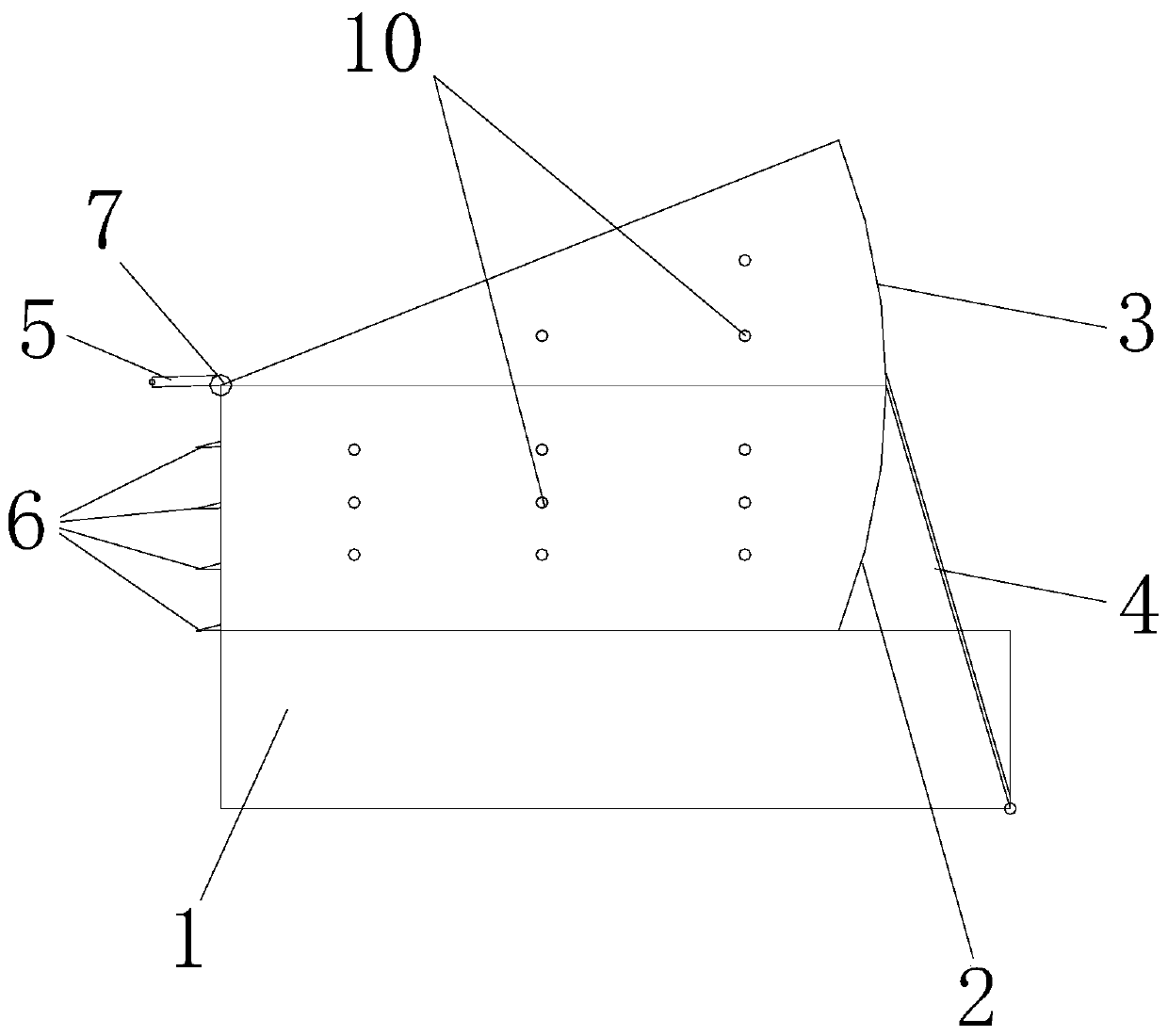
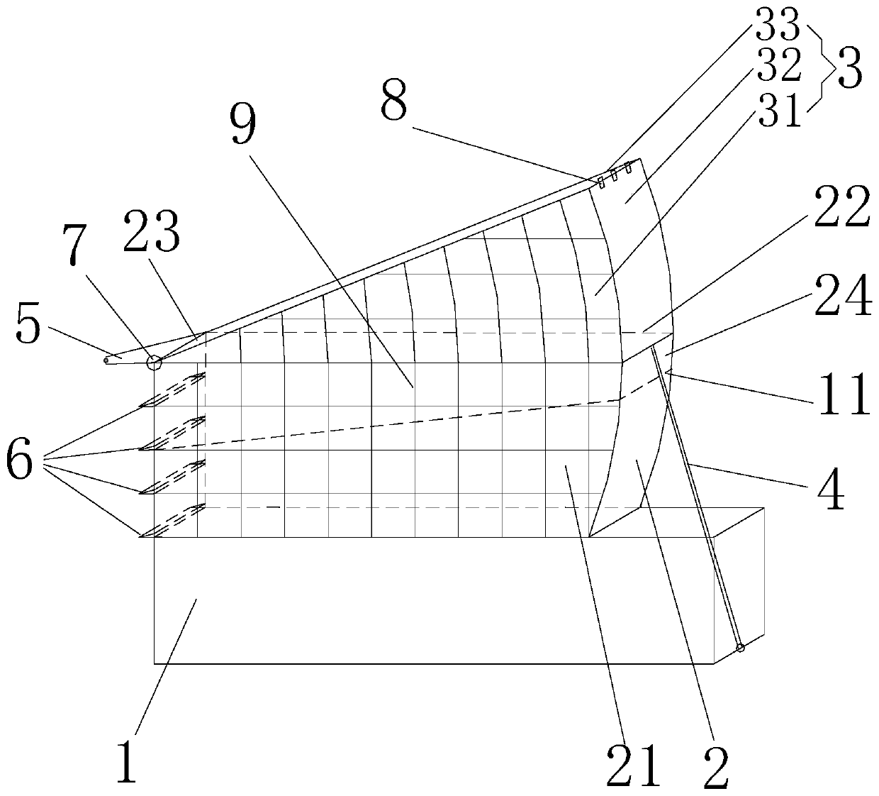
[0042] Such as figure 1 , figure 2 As shown, a slope soil mid-flow simulation device includes a runoff collection device, multiple soil mid-flow collection devices, moisture monitoring probes, and support frames, foundation grooves 2 and slope control grooves 3 arranged sequentially from bottom to top; In the supporting base groove 2 and the slope control groove 3.

[0043] The base tank 2 is a box body with an open top surface, which includes a bottom pane...


PUM

PropertyMeasurementUnit
radiusaaaaaaaaaa
angleaaaaaaaaaa

Abstract

The invention provides a slope interflow simulation device and a method for simulating interflow. An existing interflow simulation device is difficult to really reflect the actual migration conditionof the interflow. In the invention, the above problem is solved. The device comprises a foundation groove and a slope control groove. The slope control groove is located above the foundation groove and sleeves the outer side of the foundation groove. A sealing component is arranged between the foundation groove and the slope control groove. The left end of the slope control groove is hinged to thetop of the left side surface plate of the foundation groove. A right arc surface plate matches with the right side surface plate of the foundation groove. A front sector plate and a rear sector platematch with the front surface plate and the rear surface plate of the foundation groove. The slope control groove can move up and down on the outer side of the foundation groove around a rotating shaft under the effect of an angle adjusting device so as to adjust a simulation slope. The two grooves adopt a transparent hard material and are provided with observation scale nets. A soil structure filled with the device is the same with an actual slope, and the structure with a thick soil layer in the upper portion of the slope and a thin soil layer in a lower portion is presented, which can trulyreflect the actual migration condition of the interflow.

Description

technical field [0001] The invention belongs to the technical field of soil moisture migration research, and in particular relates to a soil flow simulation device on a slope and a method for simulating soil flow. Background technique [0002] Soil middle flow is a kind of water flow movement in porous media. It is the water flow flowing laterally on the interface of the soil surface or layered soil layer. It is an important part of runoff. Because soil moisture is affected by the natural environment, the change is relatively However, soil midflow plays a very important role in watershed runoff regulation, water conservation, sediment migration, nutrient loss, and calculation of watershed hydrological cycle. Therefore, the study of soil midflow is particularly critical. [0003] As for the monitoring method of soil inflow, it was firstly used in the field of hydrology and hydrogeology, mainly by speculating and calculating the change of runoff in different rainfall processes...

Claims


Application Information

Patent Timeline
Patent Type & Authority Applications(China)
IPC IPC(8): G01N33/24G01N13/00G01N13/04
Inventor 董起广张扬王欢元杜宜春雷娜刘哲何靖马建业
Owner 陕西地建土地工程技术研究院有限责任公司
Learn More