
A Parameter Measuring Method of Shaft Parts Based on the Shaft Part Parameter Measurement System

A technology for parameter measurement and shaft parts, applied in the field of shaft part parameter measurement based on the shaft part parameter measurement system, can solve problems such as high cost, high error rate, and high price

Active Publication Date: 2019-10-18
武汉联扬科技有限公司
View PDF6 Cites 0 Cited by
  • Summary
  • Abstract
  • Description
  • Claims
  • Application Information

AI Technical Summary

Problems solved by technology

Manual measurement is slow, has a high error rate, and is subject to subjective influence; the linear scan axis inspection instrument is expensive, the cost is high, and the splicing accuracy is related to the positioning accuracy of the servo motion; the image measuring instrument is used, and the measurement parameters are few. Expensive non-parallel backlight, blurred edges, unable to obtain the overall image of the part, and the automation process is not high

Method used


Image

  • A Parameter Measuring Method of Shaft Parts Based on the Shaft Part Parameter Measurement System
  • A Parameter Measuring Method of Shaft Parts Based on the Shaft Part Parameter Measurement System
  • A Parameter Measuring Method of Shaft Parts Based on the Shaft Part Parameter Measurement System

Examples


Embodiment Construction

[0091] In order to make the technical means, creative features, goals and effects achieved by the present invention easy to understand, the following will further explain how the present invention is implemented in conjunction with the accompanying drawings and specific implementation methods.

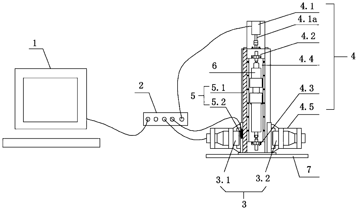
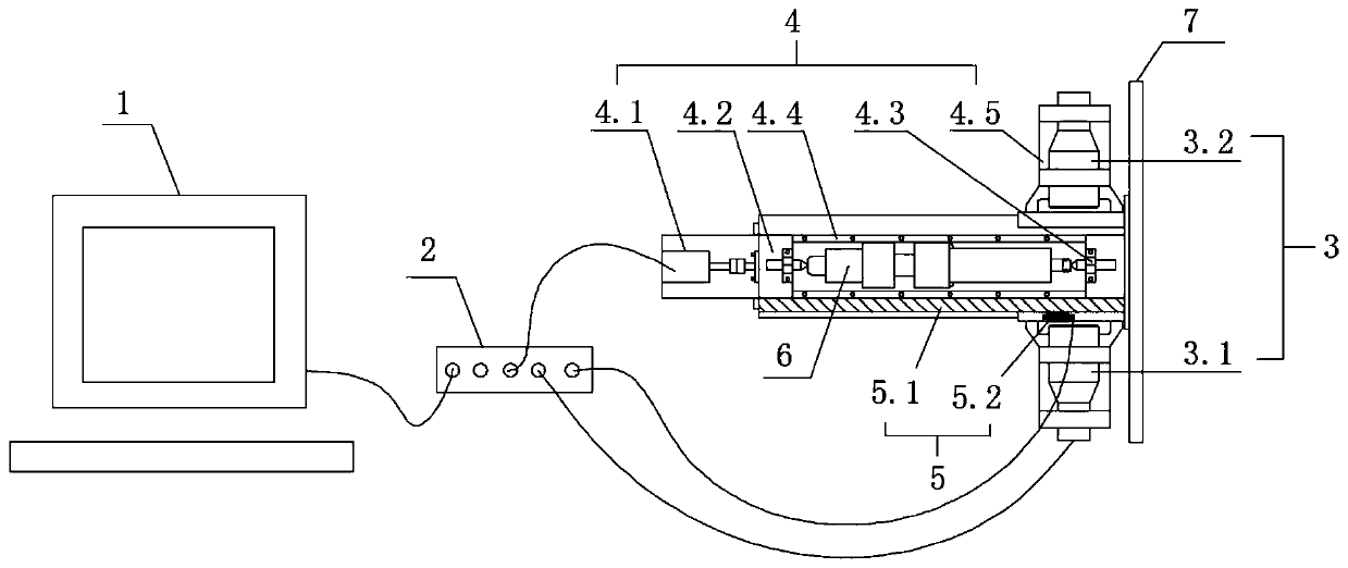
[0092] refer to figure 1 As shown, a shaft part parameter measurement system provided by the utility model includes an industrial computer 1, a hub 2, an image acquisition system 3, a motion control system 4 and a grating ruler displacement sensor 5; wherein:

[0093] The industrial computer 1 is connected with the hub 2 by wire, and is used to control the motion control system 4 to move the image acquisition system 3 to capture the images at each station of the shaft part 6 to be measured;

[0094] The hub 2 is respectively connected with the image acquisition system 3, the motion control system 4 and the grating ruler displacement sensor 5 by wire, and is used to realize the communic...


PUM


Abstract

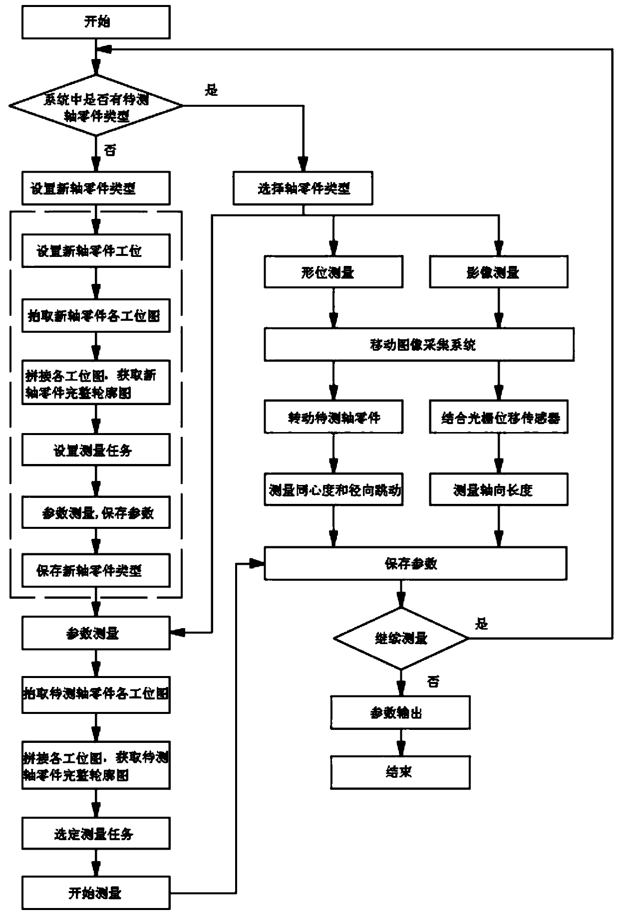
The invention discloses a shaft part parameter measurement system and method. The system includes an industrial computer, a hub, an image acquisition system, a motion control system and a grating scale. The method includes steps of determining whether to set a new shaft part type or select an existing shaft part type of the system; mounting shaft parts; selecting a measurement mode, including parameter measurement, shape and position measurement and image measurement; saving the measurement result; determining whether the quality of a to-be-tested part is qualified or not; measuring the same shaft part type or a newly-replaced shaft part type; saving parameters and outputting the result. The system and the method are advantaged in that measurement accuracy is high, the measurement speed isfast, measurement parameters are a lot, parameter measurement demands of various shaft parts can be satisfied, market changes can be better adapted, and the market prospect is broad.

Description

technical field [0001] The invention relates to the technical field of shaft part parameter measurement, in particular to a shaft part parameter measurement method based on a shaft part parameter measurement system. Background technique [0002] With the development of shaft parts technology, the dimensional accuracy requirements of processing are becoming more and more stringent, and the product styles are also increasing. To ensure product quality, it is necessary to frequently check the dimensions and various parameters of shaft parts. Since the shaft parts are the core components of mechanical equipment, the qualification of the shaft parts has an important impact on the operation of the equipment. [0003] When measuring the parameters of shaft parts, usually there are many parameters to be measured, different sizes, different tolerance requirements and high precision requirements. Manual measurement is slow, has a high error rate, and is subject to subjective influenc...

Claims


Application Information

Patent Timeline
Patent Type & Authority Patents(China)
IPC IPC(8): G01B11/00G01B11/02G01B11/27G01B11/24
Inventor 沈满德张法全周利兵闵玉瑾
Owner 武汉联扬科技有限公司
Learn More