
Ice core preparation device and method

A technology for preparing devices and ice cores, which is applied in ice making, ice making, lighting and heating equipment, etc., which can solve the problems of low ice making efficiency and difficulty in meeting the needs of rockets

Pending Publication Date: 2019-05-03
XI AN JIAOTONG UNIV
View PDF8 Cites 1 Cited by
  • Summary
  • Abstract
  • Description
  • Claims
  • Application Information

AI Technical Summary

Problems solved by technology

[0003] The traditional ice-making methods are divided into static ice-making and dynamic ice-making. Although the traditional ice-making methods are relatively mature, the ice-making efficiency of the traditional static and dynamic ice-making methods is low. Usually, the daily production of a single machine The amount of ice is less than 500kg, which is difficult to meet the needs of rocket and other engine tests

Method used


Image

  • Ice core preparation device and method
  • Ice core preparation device and method
  • Ice core preparation device and method

Examples


Embodiment 1

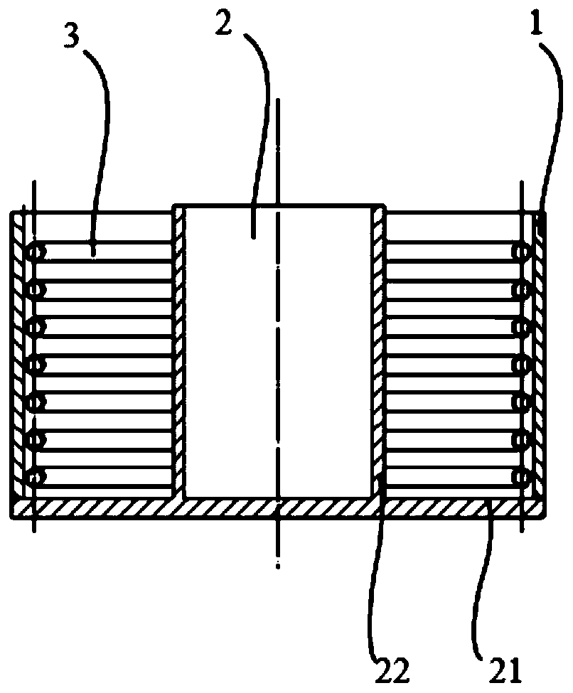
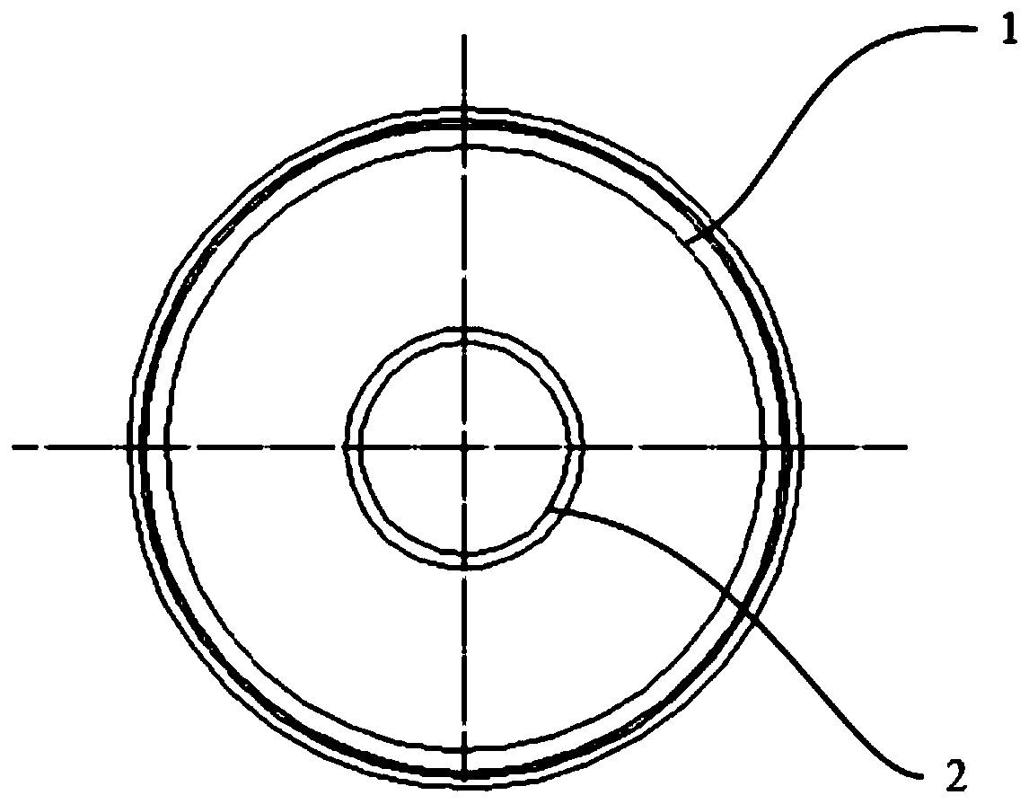
[0046] refer to figure 1 , showing the front view of an ice core preparation device provided in Embodiment 1 of the present invention, refer to figure 2 ,show figure 1 As shown in the top view of the ice core preparation device, the embodiment of the present invention is mainly described by taking the production of ice cores for solid rocket motor gas jet plume treatment systems as an example, and other types of ice core production can be referred to for implementation.

[0047] The ice core preparation device provided by the embodiments of the present invention may specifically include:

[0048] The first ice-making module 1, the first ice-making module 1 is a shell, for the solid rocket motor, the first ice-making module 1 is the shell of the importing module, which is used to make the ice core of the importing module.

[0049] The second ice-making module 2 is arranged inside the first ice-making module 1, and is used to form an inner mold when preparing ice cores. For s...

Embodiment 2

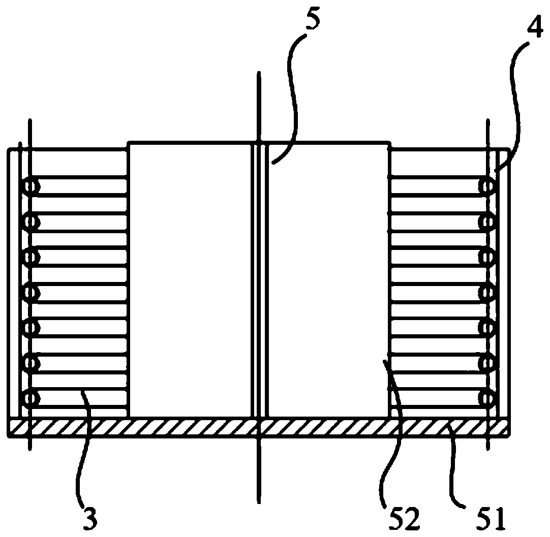
[0067] refer to image 3 , which shows the front view of an ice core preparation device provided in Embodiment 2 of the present invention, refer to Figure 4 ,show image 3 Top view of the ice core preparation apparatus shown. The difference from the first embodiment is that the ice core preparation device provided in the second embodiment is used to prepare the processing module ice core for the gas jet plume treatment system of the solid rocket motor.

[0068] Specifically, the first ice-making module 4 is a processing module shell, which is used to make ice cores of the processing module.

[0069] The second ice-making module 5 is arranged inside the first ice-making module 4, and is used to form an inner mold when preparing ice cores. For solid rocket motors, the second ice-making module 5 includes: a bottom plate 51 and a base plate 51 Connected bracket 52; wherein,

[0070] The bottom plate 52 is used for sealing connection with the first ice making module 4;

[007...


PUM


Abstract

The embodiment of the invention provides an ice core preparation device and method. The ice core preparation device comprises a first ice making module which is a shell and is used for forming an outer mold for ice core preparation, and a second ice making module which is arranged in the first ice making module and is used for forming an inner mold for ice core preparation, the first ice making module is connected with the second ice making module, an ice core preparation water trough is formed between the first ice making module and the second ice making module, and the ice core preparation water trough is used for containing ice making raw materials. A freezing module is arranged in the ice core preparation water trough, the freezing module is fixed to the inner wall of the first ice making module, and freezing liquid is fed into the freezing module. According to the ice core preparation device and method, by means of the freezing module arranged in the ice core preparation water trough, the contact area of the freezing liquid and the ice making raw materials can be increased, the freezing rate of the ice making raw materials is increased, and the ice making efficiency is improved.

Description

technical field [0001] The invention relates to the technical field of engines, in particular to an ice core preparation device and method. Background technique [0002] With the widespread use of engines, while enjoying the huge propulsion generated by the engines, people are also enduring the pollution and damage to the ecological environment brought by their tail flames. Therefore, some engine gas jet tail flame treatment systems have appeared. The system needs to use a large amount of ice to make the plume cooling device, and the demand for ice is very large. [0003] The traditional ice-making methods are divided into static ice-making and dynamic ice-making. Although the traditional ice-making methods are relatively mature, the ice-making efficiency of the traditional static and dynamic ice-making methods is low. Usually, the daily production of a single machine The amount of ice is less than 500kg, which is difficult to meet the needs of rocket and other engine tests...

Claims


Application Information

Patent Timeline
IPC IPC(8): F25C1/04
Inventor 王世琥张平吴德乾
Owner XI AN JIAOTONG UNIV
Learn More