Knife switch control loop monitoring method and system

A technology of control loop and detection method, applied in the field of electric power, can solve the problem that the knife switch cannot find the control loop, operation delay, etc., and achieve the effect of speeding up the search time, reducing the operation delay, and quickly positioning

Active Publication Date: 2019-04-30
中国南方电网有限责任公司超高压输电公司南宁监控中心
View PDF8 Cites 3 Cited by
  • Summary
  • Abstract
  • Description
  • Claims
  • Application Information

AI Technical Summary

Problems solved by technology

Different from the switch which has a complete control circuit disconnection monitoring circuit, all current knife switches do not have a monitoring circuit. As a result, the control circuit cannot be found to have problems under the operating condition of the knife switch. It can only be found at the moment of operation, resulting in operation delays.

Method used


Image

  • Knife switch control loop monitoring method and system
  • Knife switch control loop monitoring method and system
  • Knife switch control loop monitoring method and system

Examples


Embodiment

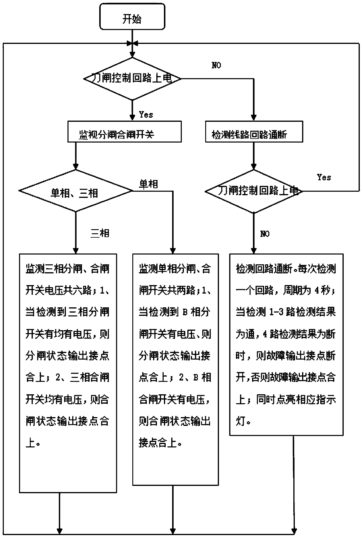
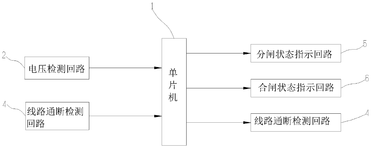
[0027] refer to figure 1 As shown, the knife switch control loop monitoring method provided in this embodiment includes:


PUM


Abstract

The invention discloses a knife switch control loop monitoring detection method and system. The method comprises the steps of: detecting and judging whether a knife switch control loop is powered offor not, monitoring the on-off state of the knife switch opening and closing loop if the knife switch control loop is in a power-on state, judging whether the opening and closing loop is switched on ornot, and outputting a state indication if the opening and closing loop meets an opening and closing operation condition; and if the knife switch control loop is in the power-off state, detecting theon-off state of the knife switch control loop, judging whether each section of the opening and closing control loop that should be on is in an on state or not, judging whether the section which shouldnot be on is in an off state or not, and outputting a state indication. By adopting the method provided by the invention, the opening and closing loop state of the knife switch control loop can be monitored, loop faults can be found before knife switch operation, and a knife switch also has a loop disconnection monitoring function at the same level as that of a switch; knife switch control loop fault detection can be realized when a problem occurs, and a loop fault section can be quickly positioned, so that operation delay is reduced.

Description

technical field [0001] The invention relates to the field of electric power technology, in particular to a monitoring system and a monitoring method for a knife switch control circuit. Background technique [0002] Knife switch failure is the most frequently encountered and most common failure in switching operations, and the operation delay caused by knife switch failure accounts for the largest part of the operation delay. Knife switch faults are divided into mechanical faults and circuit faults, and circuit faults account for about half of them. Different from the switch which has a complete control circuit disconnection monitoring circuit, all the current knife switches do not have a monitoring circuit, which leads to the failure of the control circuit to be found under the operating condition of the knife switch. It can only be found at the moment of operation, resulting in operation delays. . Contents of the invention [0003] The purpose of the present invention i...

Claims


Application Information

Patent Timeline
Patent Type & Authority Applications(China)
IPC IPC(8): G01R31/327G01R31/02
CPCG01R31/327G01R31/50
Inventor 廖华钟文明滕永泰朱明红袁卫义陈方之钟晖彭伟梁阳陈磊
Owner 中国南方电网有限责任公司超高压输电公司南宁监控中心
Why Eureka
Try Eureka