
Display screen attachment device and method

A bonding device and display technology, applied to household components, household appliances, other household appliances, etc., can solve the problems of relative contact movement between flexible film and curved surface protection cover, defective products, etc., to reduce defective products and avoid air bubbles wrinkled effect

Pending Publication Date: 2019-04-23
汪恒坤
View PDF0 Cites 17 Cited by
  • Summary
  • Abstract
  • Description
  • Claims
  • Application Information

AI Technical Summary

Problems solved by technology

[0003] For the existing production equipment of curved display screens, it is generally designed for curved display screens with an obtuse angle structure greater than 90 degrees. For the lamination between the protective covers, the flexible film is easy to contact with the curved edge of the curved protective cover, and it is easy to cause relative contact movement between the flexible film and the curved protective cover during the lamination process, resulting in defective products

Method used


Image

  • Display screen attachment device and method
  • Display screen attachment device and method
  • Display screen attachment device and method

Examples


Embodiment 1

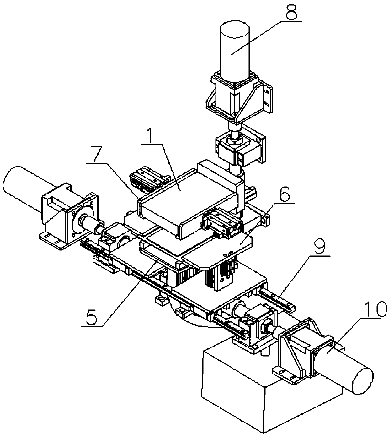
[0038] Such as Figure 1 to Figure 8 as shown, Figure 1 to Figure 8 The fit and non-fit in are the fit and non-fit between the curved surface protection cover and the flexible film. The display bonding device of the present invention includes an upper cavity and a lower cavity, the upper cavity and the lower cavity are arranged in cooperation, and both the upper cavity and the lower cavity can move up and down; when When the upper cavity and the lower cavity are closed, a closed space is formed in the upper cavity and the lower cavity; the upper cavity is provided with a placement platform 1 and a curved protective cover 2, and the lower cavity The body is provided with a flexible film 3, a carrier tape 4, and a lifting and pressing part 5; the placing platform 1 is used to place the curved surface protection cover 2, the flexible film 3 is placed on the carrier tape 4, and the carrier The belt 4 is placed on the lifting and pressing part 5, and the flexible film 3 and the ...

Embodiment 2

[0046] Such as Figure 1 to Figure 4 As shown, the placement platform 1 is used to support the curved surface protection cover 2, the placement platform 1 is generally rectangular and has a certain thickness; the placement platform 1 is connected to the lifting device 8 inside the closed space , the placing platform 1 can be moved down toward the lifting and pressing part 5 through the lifting device 8 . The airbag 51 is arranged on the upper part of the lifting and pressing part 5 ; the height of the airbag 51 can be adjusted through the lifting and pressing part 5 .

[0047] The lower end surface of the placement platform 1 is provided with an installation groove for accommodating the curved surface protection cover 2, so that the support curved surface protection cover 2 can be fixed; The vacuum holes on the surface of the curved protection cover 2 are used for absorbing and supporting the curved protection cover 2 .

[0048] The gripping device is arranged on both sides ...

Embodiment 3

[0064] The limiting device 7 includes a fixed plate 71, a limiting plate 72 and a third cylinder 73 arranged on the placing platform 1, the fixing plate 71 is fixed on the placing platform 1, and the limiting plate 72 It is fixedly arranged at the end of the telescopic rod of the third air cylinder 73, and the third air cylinder 73 is fixedly arranged on the fixed plate 71, and the limit plate 72 and the mounting plate 72 can be adjusted through the third air cylinder 73. The relative position of the slot.

[0065] The limiting plate 72 is symmetrically arranged on both sides of the installation groove, that is, the limiting plate 72 corresponds to the setting of the curved edge 21 of the curved surface protection cover, and the bottom end of the limiting plate 71 exceeds the placement position. The bottom end surface of the platform 1 ensures the contact between the limiting plate 71 and the carrier tape 4 , so that the carrier tape 4 maintains a certain bending state.

[00...


PUM


Abstract

The invention discloses a display screen attachment device and method. The device comprises an upper cavity and a lower cavity which are matched with each other; both the upper cavity and the lower cavity can move up and down; the upper cavity is provided with a placement platform and a curved surface protective cover plate; the lower cavity is provided with a flexible membrane, a carrier band andan ascending-descending pressurizing portion; the placement platform is used for placement of the curved surface protective cover plate; the flexible membrane is placed on the carrier band; the carrier band is of an elastic and soft platy structure; the carrier band is placed on the ascending-descending pressurizing portion; the flexible membrane and the curved surface protective cover plate arearranged by corresponding to each other up and down; and through adjustment of the height positions of the placement platform and the ascending-descending pressurizing portion, attachment between theflexible membrane and the curved surface protective cover plate is achieved. Flexible membrane attachment is performed on the curved surface protective cover plate with the right-angle edge or the acute angle edge, under the air bag expansion deformation and the action of a limiting device, online contact between the end of the flexible membrane and the edge position of the curved surface of the curved surface protective cover plate is avoided, and the defective products of production are reduced.

Description

technical field [0001] The invention relates to the technical field of screen production, in particular to a display bonding device and bonding method. Background technique [0002] With the hot sale of Samsung Galaxy S6 Edge and Galaxy S7 Edge models, the curved surface display is gradually rising under the drive of its brand effect. At the same time, with the rapid development of OLED technology in recent years, it can be predicted that curved surface TVs, curved surface mobile phones, and curved surface computers will be in the future. A large number emerged. [0003] For the existing production equipment of curved display screens, it is generally designed for curved display screens with an obtuse angle structure greater than 90 degrees. For the lamination between the protective covers, the flexible film is likely to contact the curved edge of the curved protective cover first, and during the lamination process, it is easy to cause relative contact movement between the f...

Claims


Application Information

Patent Timeline
IPC IPC(8): B29C63/02B29L31/34
CPCB29C63/02B29L2031/3437
Inventor 汪恒坤
Owner 汪恒坤
Learn More