


Quick Research
Generate reliable direction feasibility study reports for your R&D in just a few steps.

Technical Q&A
Discover and master advanced knowledge NOW. Basics, ideas, possibilities, all at once.

Find Solutions
As an expert in R&D theories, this can generate solutions to your technical problems instantly.

Evaluate Feasibility
Analyze your overall solution with one click, know your potential R&D risks in advance.

Monitor Landscape
Get weekly tech updates, stay abreast of the latest tech innovations and key insights.
FPGA operation box convenient to move
A technology for operating boxes and boxes, which is applied in the FPGA field, can solve problems such as operators falling down, and achieve the effect of preventing the danger of falling
- Summary
- Abstract
- Description
- Claims
- Application Information
AI Technical Summary
Problems solved by technology
Method used
Image

Examples
Embodiment 1
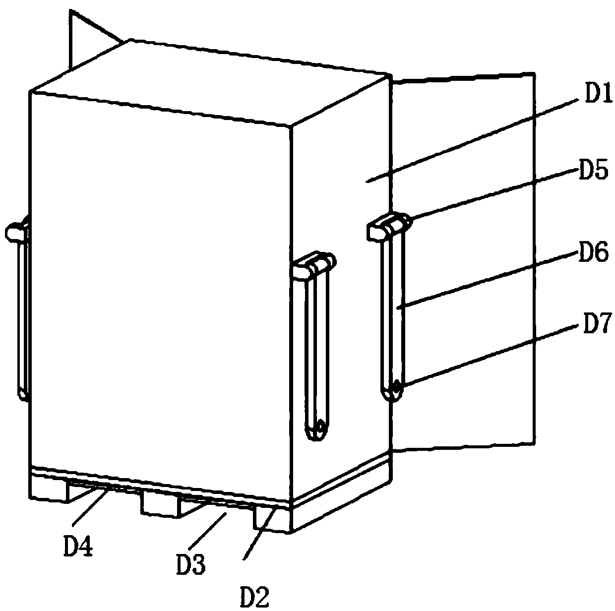
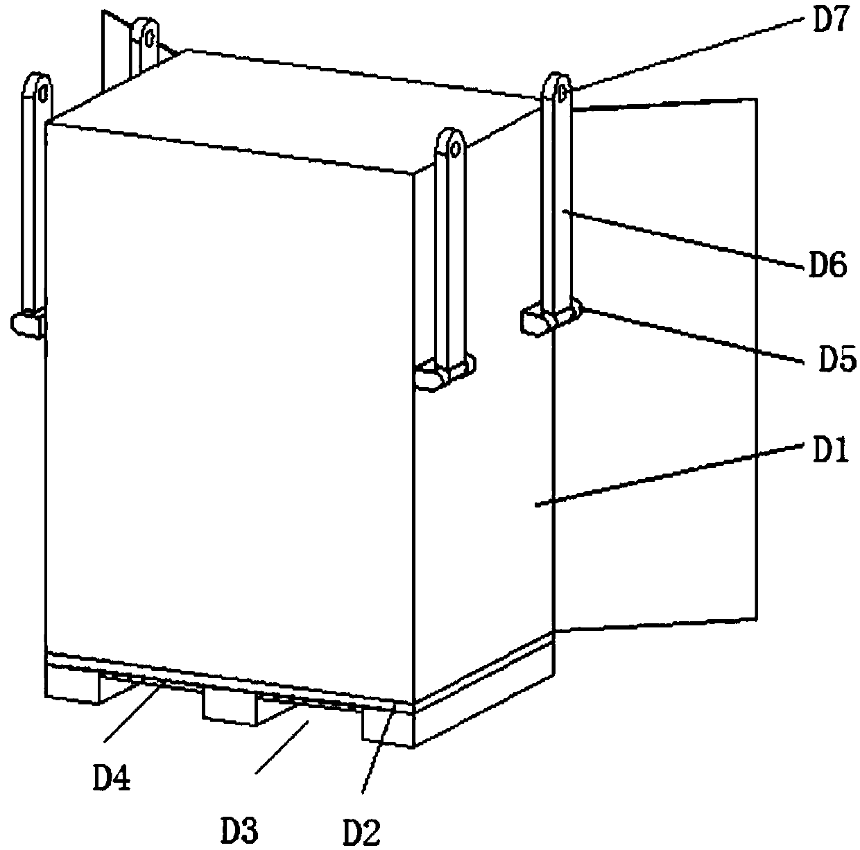
[0014] Such as Figure 1-Figure 2 As shown, the FPGA operation box that is beneficial to move includes a box body D1, and the lower wall plate D2 of the box body D1 has a moving channel D3 at a lower position, and the box body D1 is located on the side walls on both sides of the cover plate by pressing A pair of hangers D5 are welded on each mirror image of the horizontal extension, and the hangers D5 are connected to the connecting bar D6. The bar D6 can rotate in a semicircle with the hanger D5 as the center of the circle.
[0015] The working principle of this embodiment is:
[0016] When transporting by means of transport, the transport tool can be moved by inserting the workplace strips of the transport means into the moving ditch 2 at the lower end of the box body 1; when moving by means of transport, the operator can wrap the curved part around the two pairs of connecting bars The arc-shaped hanging ear D7 of D6, the traction connecting bar D6 is rotated toward a high...
Embodiment 2
[0020] Such as Figure 1-Figure 2 As shown, the FPGA operation box that is beneficial to move includes a box body D1, and the lower wall plate D2 of the box body D1 has a moving channel D3 at a lower position, and the box body D1 is located on the side walls on both sides of the cover plate by pressing A pair of hangers D5 are welded on each mirror image of the horizontal extension, and the hangers D5 are connected to the connecting bar D6. The bar D6 can rotate in a semicircle with the hanger D5 as the center of the circle.
[0021] The outer wall of the lower wall board D2 in the moving ditch D3 is adhered with a frosted paper D4, which is helpful for the protection of the lower wall board D2 by the moving bracket of the transport tool.
[0022] The working principle of this embodiment is:
[0023] When transporting by means of transport, the transport tool can be moved by inserting the workplace strips of the transport means into the moving ditch 2 at the lower end of the...
PUM
 Abstract
Description
Claims
Application Information
 - R&D Engineer
- R&D Manager
- IP Professional
- Industry Leading Data Capabilities
- Powerful AI technology
- Patent DNA Extraction
Browse by: Latest US Patents, China's latest patents, Technical Efficacy Thesaurus, Application Domain, Technology Topic, Popular Technical Reports.
© 2024 PatSnap. All rights reserved.Legal|Privacy policy|Modern Slavery Act Transparency Statement|Sitemap|About US| Contact US: help@patsnap.com