
Low-damping ratio flow-induced vibration experimental device based on electronic spring

An electronic spring and experimental device technology, applied in the field of experimental devices, low damping ratio flow-induced vibration experimental devices based on electronic springs, can solve the problems of incomplete simulation system linear viscous damping, changing physical springs, etc., to achieve moderate cost, Accurate and rapid change, reliable experimental data effect

Inactive Publication Date: 2019-04-16
HARBIN ENG UNIV
View PDF6 Cites 1 Cited by
  • Summary
  • Abstract
  • Description
  • Claims
  • Application Information

AI Technical Summary

Problems solved by technology

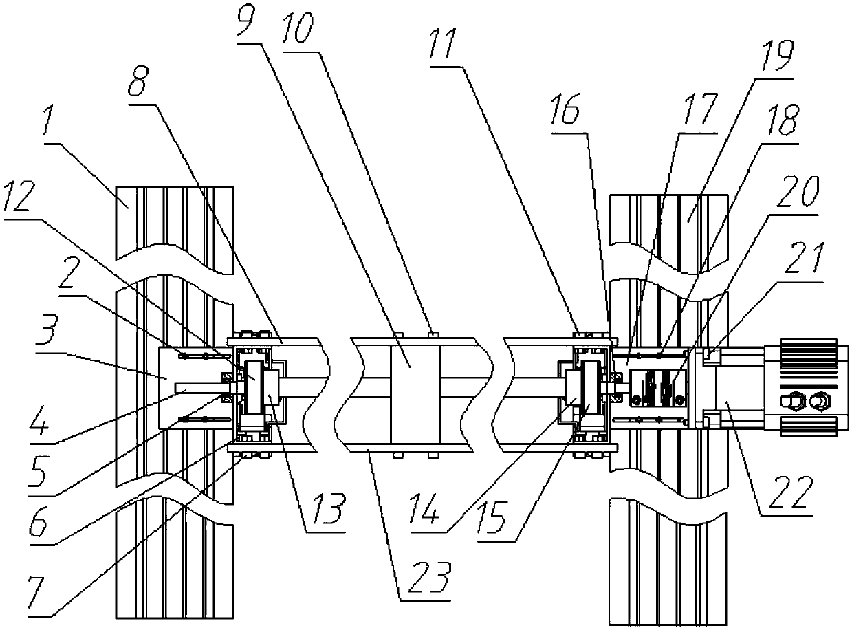
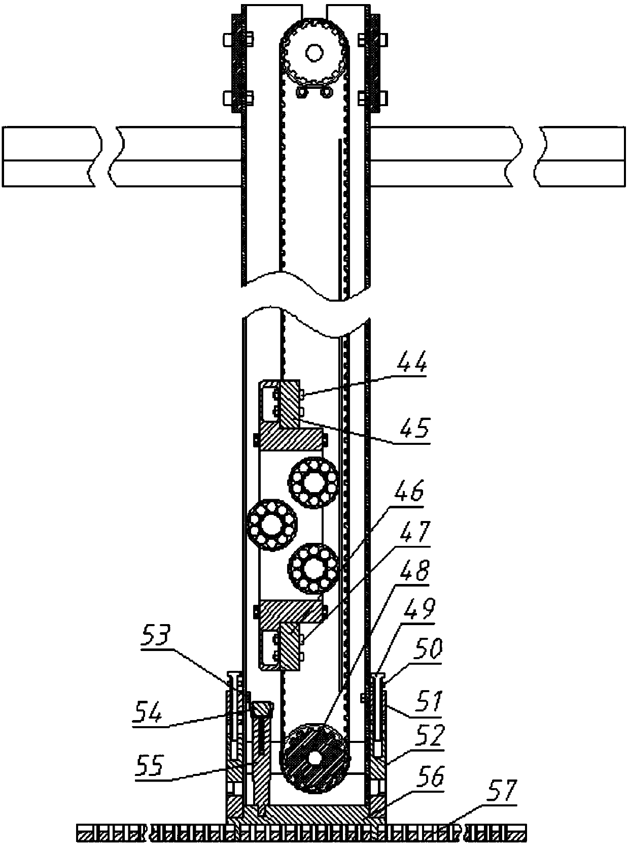
[0004] The purpose of the present invention is to provide a low damping ratio flow-induced vibration experimental device based on electronic springs in order to overcome the shortcomings of traditional flow-induced vibration experimental equipment, such as the difficulty of changing physical springs and damping, and the inability to completely simulate the linear viscous damping of the system.

Method used


Image

  • Low-damping ratio flow-induced vibration experimental device based on electronic spring
  • Low-damping ratio flow-induced vibration experimental device based on electronic spring
  • Low-damping ratio flow-induced vibration experimental device based on electronic spring

Examples


Embodiment Construction

[0021] The present invention will be further described in detail below in conjunction with the accompanying drawings and specific embodiments.

[0022] The purpose of the present invention is to disclose a low damping ratio flow-induced vibration experimental equipment based on the electronic spring Vck, which is suitable for energy collection of vortex-induced vibration at low flow rates. It is a modular design, and after debugging, it can work with multiple modules to meet the experimental requirements.

[0023] The experimental equipment mainly includes two parts, the mechanical vibration system and the Vck system. It is characterized by a modular design and can conduct experiments with multiple modules at the same time.

[0024] The experimental equipment mainly includes the following two parts:

[0025] (1) Mechanical vibration system The mechanical vibration system consists of a cylindrical vibrator with PTC, a slider, a timing belt, a timing belt drive wheel, a base, a...


PUM


Abstract

The invention provides a low-damping ratio flow-induced vibration experimental device based on an electronic spring. The device comprises a cylindrical vibrator, a slider, a slide rail, a timing beltand timing belt conveying wheels. Upper and lower ends of the slide rail are fixedly connected. Both ends of the cylindrical vibrator are connected with the slider. The slider matches the slide rail.Timing belt conveying wheels are arranged above and below the slide rail. The timing belt conveying wheels match the timing belt. Both ends of the slider are connected with the timing belt. A transmission wheel on the upper side of the slide rail is connected with the rotating shaft of the cylindrical vibrator. The rotating shaft is connected with a Vck system. The shortcomings that a traditionalflow-induced vibration experimental device is difficult to change physical springs and damping and cannot completely simulate the linear viscous damping of a system are overcome. An experiment can change parameters accurately and quickly, and acquired experimental data are more reliable.

Description

technical field [0001] The invention relates to an experimental device, in particular to an electronic spring-based low damping ratio flow-induced vibration experimental device, which belongs to the field of new energy sources. Background technique [0002] In the early VIVACE systems of the Marine Renewable Energy Lab (MRELab), physical springs and mechanical dampers were used. However, the vibrator will have a large energy loss in order to overcome the resistance, so the system damping must be minimized to obtain higher energy. Foreign countries have tried to use electronic components instead of solid springs and dampers. One of the representatives is VCTA (MIT). The equipment uses feedback control and real-time measurement and calculation of vortex-induced hydrodynamic forces; but in actual operation, VCTA is relatively The spring-damper system has a phase lag of 12 degrees and 9 degrees; subsequent related equipment has the same problem. In order to meet the experiment...

Claims


Application Information

Patent Timeline
Patent Type & Authority Applications(China)
IPC IPC(8): G01M7/02G01M10/00
CPCG01M7/022G01M10/00
Inventor 孙海陈芝赟孙丽萍
Owner HARBIN ENG UNIV
Learn More