
Pressure switch valve

A pressure switch and valve body technology, which is applied in the field of pressure switch valves, can solve the problems of over-reliance on circuit systems, induction repetition, and high production costs, and achieve the effects of avoiding induction repetition, saving costs, and getting rid of excessive dependence

Pending Publication Date: 2019-04-16
YUYAO SANSHUN WATER PURIFICATION TECH CO LTD
View PDF0 Cites 1 Cited by
  • Summary
  • Abstract
  • Description
  • Claims
  • Application Information

AI Technical Summary

Problems solved by technology

[0002] What is common in the market at present is that the solenoid valve is controlled by an electromagnetic device. Its working process is: the high-voltage switch, solenoid valve, water pump, etc. are connected with the circuit board to form a complete opening and closing system. When the internal pressure increases, the high pressure switch is under great pressure and then the circuit is disconnected. After the circuit is disconnected, the solenoid valve closes and the water pump stops working. It first uses the high pressure switch to sense the pressure to open and close the circuit, and uses the circuit to further control the water pump and the pump. The opening and closing of the solenoid valve has high production costs, is too dependent on the circuit system, and there are repeated phenomena in the induction, and the circuit is prone to "false breaks"

Method used


Image

  • Pressure switch valve
  • Pressure switch valve
  • Pressure switch valve

Examples


Embodiment 1

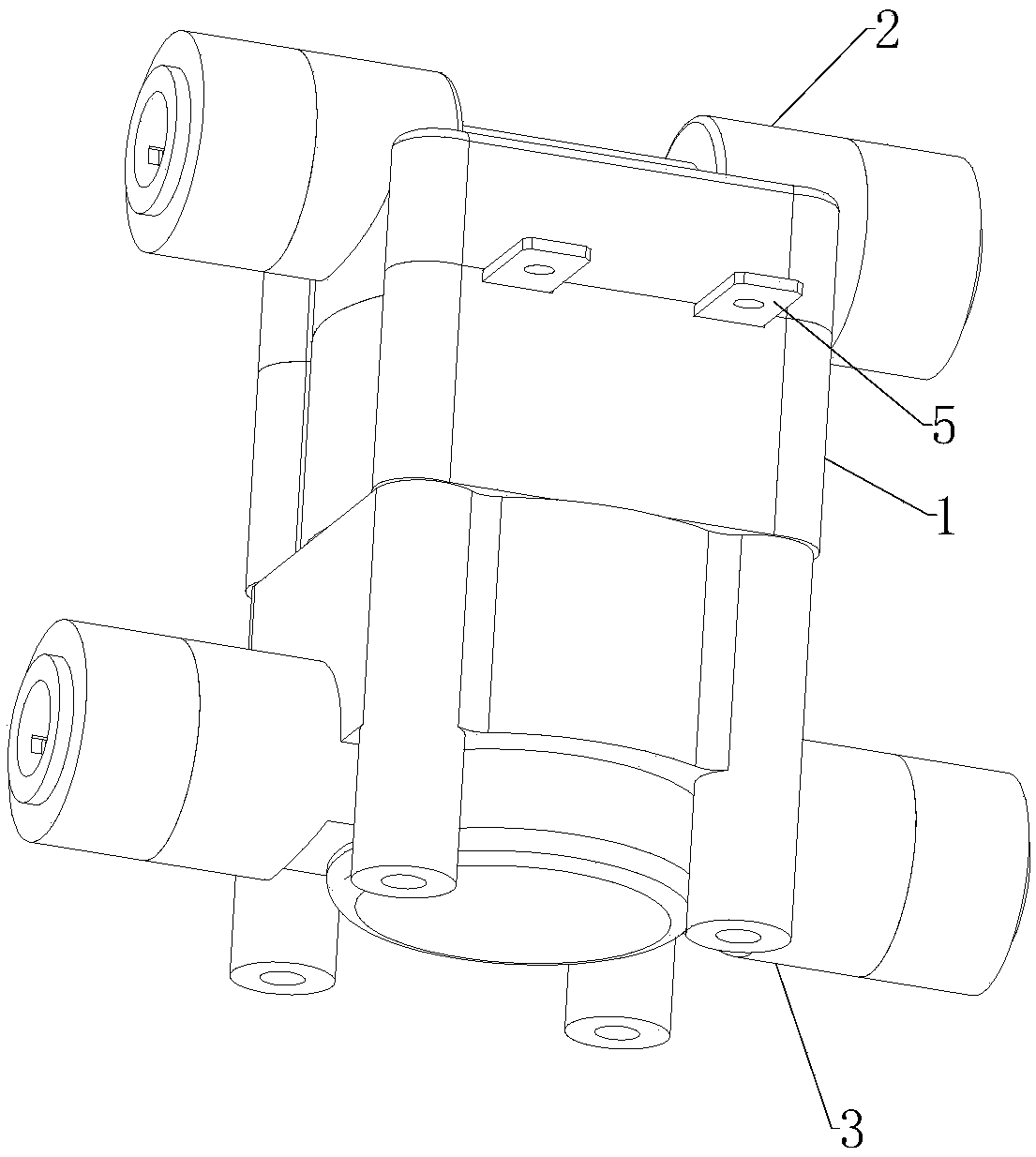
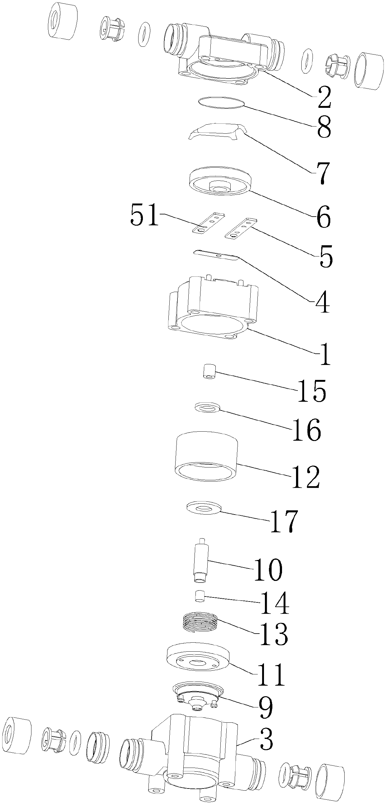
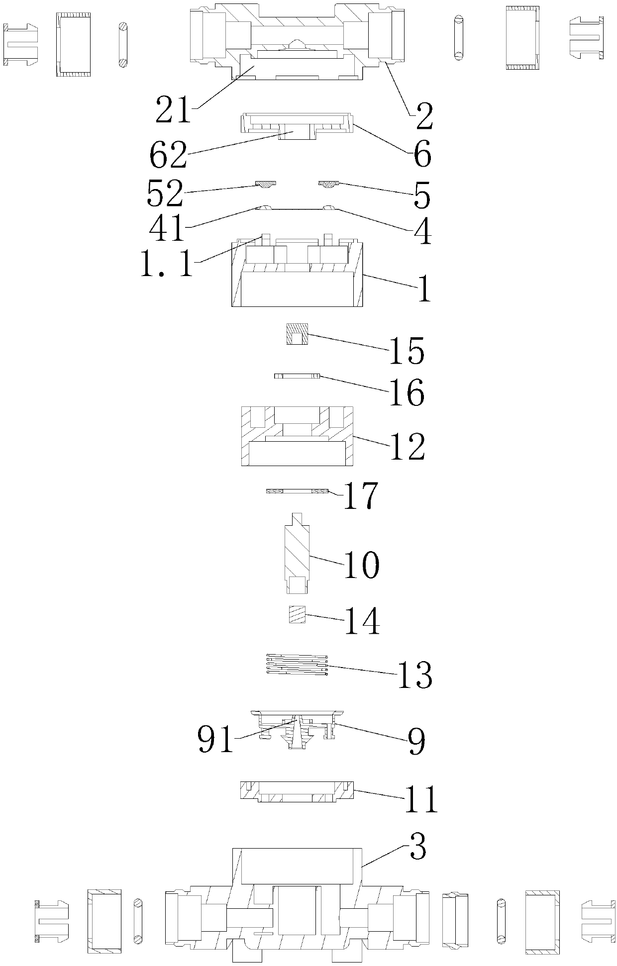
[0023] Embodiment one, such as figure 1 — Figure 4 As shown, the pressure switch valve includes a valve body 1, the upper and lower ends of the valve body 1 are respectively installed with a pure water pipeline 2 and a raw water pipeline 3, and a movable conductive piece 4 is placed in the valve body 1 and a connection with the movable conductive piece 4 is placed. The conductive piece 5 is fixed, a cover plate 6 is provided on the top of the valve body 1, and a shrapnel 7 is arranged inside the cover plate 6. The bottom end of the pure water pipeline 2 covers the cover plate 6, and a spring piece is arranged inside the bottom end of the pure water pipeline 2. The sealing diaphragm 8 on the 7, the top of the raw water pipeline 3 is provided with a valve core 9, the middle of the valve core 9 has a pilot hole 91, and a pilot hole 91 for opening or closing is provided between the valve core 9 and the valve body 1 and can An elastic return device that moves up and down, the ela...

Embodiment 2

[0034] Embodiment two: if Figure 5 As shown, the difference between Embodiment 2 and Embodiment 1 is that it removes the soft block 14 and the sheath 15, the bottom end of the push rod 10 is directly used to block the pilot hole 91 in the middle of the valve core 9, and the top end is directly located under the shrapnel 7 .


PUM


Abstract

The invention discloses a pressure switch valve comprising a valve body. The upper end and the lower end of the valve body are provided with a pure water pipeline and a raw water pipeline correspondingly. A movable electricity conducting plate and a fixed electricity conducting plate connected with the movable electricity conducting plate are arranged in the valve body. A cover plate is arranged at the top end of the valve body. An elastic sheet is arranged inside the cover plate. The bottom end of the pure water pipeline covers the cover plate. A seal membrane pressing the elastic sheet is arranged inside the bottom end of the pure water pipeline. A valve element is arranged in the top end of the raw water pipeline. A pilot hole is formed in the middle of the valve element. An elastic resetting device which is used for opening or closing the pilot hole and can move up and down is arranged between the valve element and the valve body. The elastic resetting device comprises a push rod used for abutting against the elastic sheet and fixed to the movable electricity conducting sheet. The pressure switch valve omits an electromagnetic device, saves cost, avoids the induction repetitionphenomenon and gets rid of excessive dependence on a circuit system, pressure is utilized to control switching on and off of a circuit and the valve, and the use effect is better.

Description

technical field [0001] The invention relates to a valve, in particular to a pressure switch valve. Background technique [0002] What is common in the market at present is that the solenoid valve is controlled by an electromagnetic device. Its working process is: the high-voltage switch, solenoid valve, water pump, etc. are connected with the circuit board to form a complete opening and closing system. When the internal pressure increases, the high pressure switch is under great pressure and then the circuit is disconnected. After the circuit is disconnected, the solenoid valve closes and the water pump stops working. It first uses the high pressure switch to sense the pressure to open and close the circuit, and uses the circuit to further control the water pump and the pump. The opening and closing of the solenoid valve has high production costs, is too dependent on the circuit system, and there are repeated phenomena in the induction, and the circuit is prone to "false bre...

Claims


Application Information

Patent Timeline
Patent Type & Authority Applications(China)
IPC IPC(8): F16K31/02
CPCF16K31/02
Inventor 卢友国
Owner YUYAO SANSHUN WATER PURIFICATION TECH CO LTD
Learn More