Rotary net head removing machine
The technology of a bulkhead machine and a rotary screen is applied in printing machines, general parts of printing machinery, printing and other directions, which can solve problems such as low efficiency of removing bulkheads, reduce soaking steps, increase heating area, and increase the effect of heating area.
- Summary
- Abstract
- Description
- Claims
- Application Information
AI Technical Summary
Problems solved by technology
Method used
Image
Examples
Embodiment 1
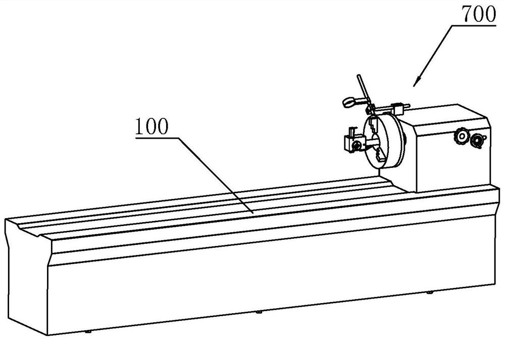
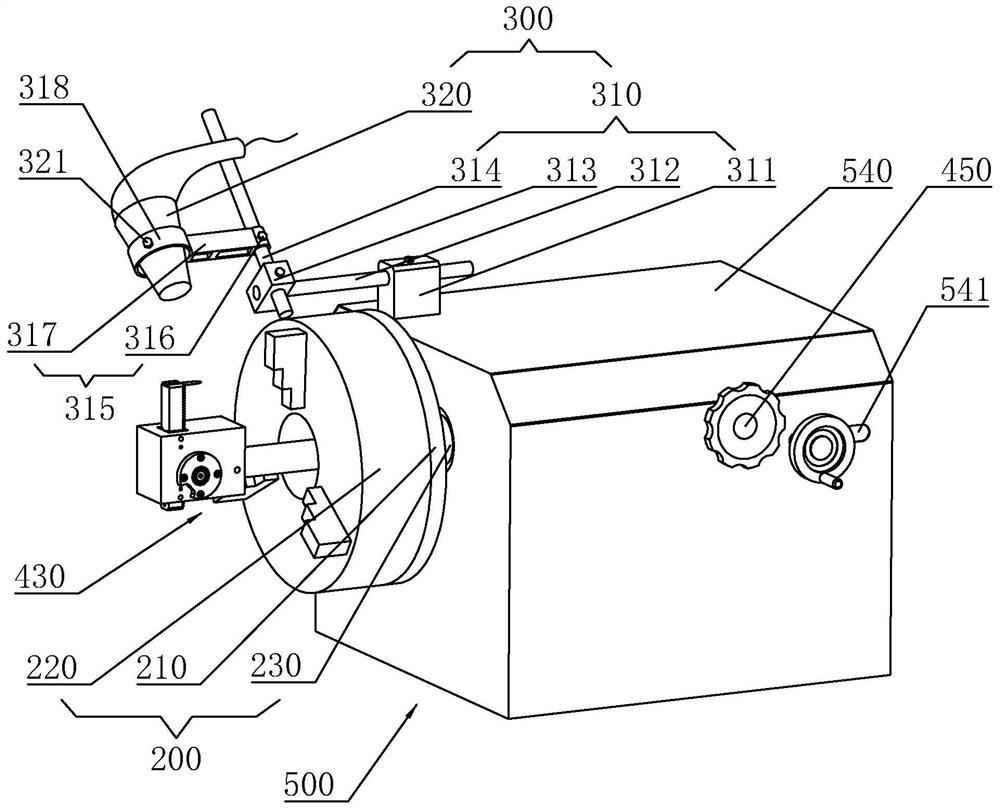
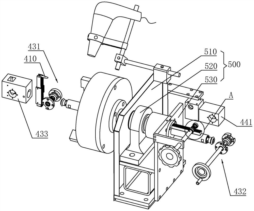
[0046] A kind of rotary screen de-blocking machine, refer to figure 1 , including a rectangular parallelepiped working table 100, one end of the working table 100 is provided with a bulky head disengaging device 700 for clamping the bulky head and separating the bulky head from the round nickel mesh. refer to figure 2 The bulkhead detachment device 700 includes a mounting plate set 500 fixedly connected to one end of the workbench 100, a bulkhead clamping mechanism 200 rotatably connected to the mounting plate set 500, and a connecting point facing the bulkhead and the round nickel mesh connected to the mounting plate set 500. The heating mechanism 300, and the peeling mechanism 400 for peeling off the bulkhead and the round nickel mesh.
[0047] combine figure 2 with image 3 , the mounting plate group 500 includes a first mounting plate 510, a support base 520 and a second mounting plate 530 vertically connected to the upper surface of the workbench 100, and the first m...
Embodiment 2
[0066] A kind of rotary screen de-blocking machine, refer to Figure 7 The difference from Embodiment 1 is that the connecting piece 315 connected to the second connecting rod 314 includes a mounting rod 317 with one end sleeved outside the second connecting rod 314, a positioning member 316 connected to the mounting rod 317, and the mounting rod 317 is another One end is connected with an arc-shaped heating wire 330 , and the heating wire 330 faces the joint between the bulkhead and the round nickel mesh, and is adapted to the shape of the bulkhead. An end of the mounting rod 317 away from the second connecting rod 314 is integrally connected with a mounting piece 340 , and a middle position of the heating wire 330 is fixedly connected to the mounting piece 340 by bolts.
[0067] The mounting piece 340 is provided with a plurality of abutting bolts 350, which pass through the mounting piece 340 and abut against the heating wire 330, so as to adjust the arc of the heating wire...
Embodiment 3
[0069] A kind of rotary screen de-blocking machine, refer to Figure 8 The difference from Embodiment 1 or Embodiment 2 is that the connecting member 315 includes a cylinder 370, the cylinder body of the cylinder 370 is fixedly connected with the second connecting rod 314, and the piston rod is fixedly connected with the heating element. The heating element can be an electric blower 320 or an electric heating wire 330 . For the specific installation method of the electric blower 320 or electric heating wire 330 , refer to Embodiment 1 or Embodiment 2. The first mounting plate 510 is provided with a detection piece for detecting the position of the electric blower 320 or the heating wire 330 , and the detection piece is electrically connected with the cylinder 370 to control the start and stop of the cylinder 370 . The detection part can adopt an infrared sensor, and the infrared sensor detects that the hair dryer 320 or the heating wire 330 has arrived at a set position, and o...
PUM
 Abstract
Description
Claims
Application Information
 - R&D
- Intellectual Property
- Life Sciences
- Materials
- Tech Scout
- Unparalleled Data Quality
- Higher Quality Content
- 60% Fewer Hallucinations
Browse by: Latest US Patents, China's latest patents, Technical Efficacy Thesaurus, Application Domain, Technology Topic, Popular Technical Reports.
© 2025 PatSnap. All rights reserved.Legal|Privacy policy|Modern Slavery Act Transparency Statement|Sitemap|About US| Contact US: help@patsnap.com


