
Automatic lifting type electronic rotary knob gear shifter assembly

An automatic lifting and shifter technology, which is applied in the direction of transmission control, components with teeth, belts/chains/gears, etc., can solve the problems of rigid button operation, poor operation experience, and large space occupation, and achieve high-end High reliability, comfortable operation feel, and compact structure

Pending Publication Date: 2019-04-12
宁波德普隆汽车系统有限公司
View PDF0 Cites 1 Cited by
  • Summary
  • Abstract
  • Description
  • Claims
  • Application Information

AI Technical Summary

Problems solved by technology

[0003] The mechanical shifting device has a complex structure and takes up a lot of space; and the use of an electronic shifter will improve the grade of the car, so more and more vehicle manufacturers switch to electronic shifters. Some existing electronic shifters The shift operation is controlled by buttons, and the shift command is sent by the button to the PCB board, and then the electronic signal is sent by the PCB board to control the actuator to complete the shift, but the button operation seems a bit rigid
At present, there is also a knob-type shifter on the market, but the general operation experience is poor and the aesthetics is not high, so it cannot better meet the needs of drivers.

Method used


Image

  • Automatic lifting type electronic rotary knob gear shifter assembly
  • Automatic lifting type electronic rotary knob gear shifter assembly
  • Automatic lifting type electronic rotary knob gear shifter assembly

Examples


Embodiment Construction

[0029] Embodiments of the present invention will be described in further detail below in conjunction with the accompanying drawings.

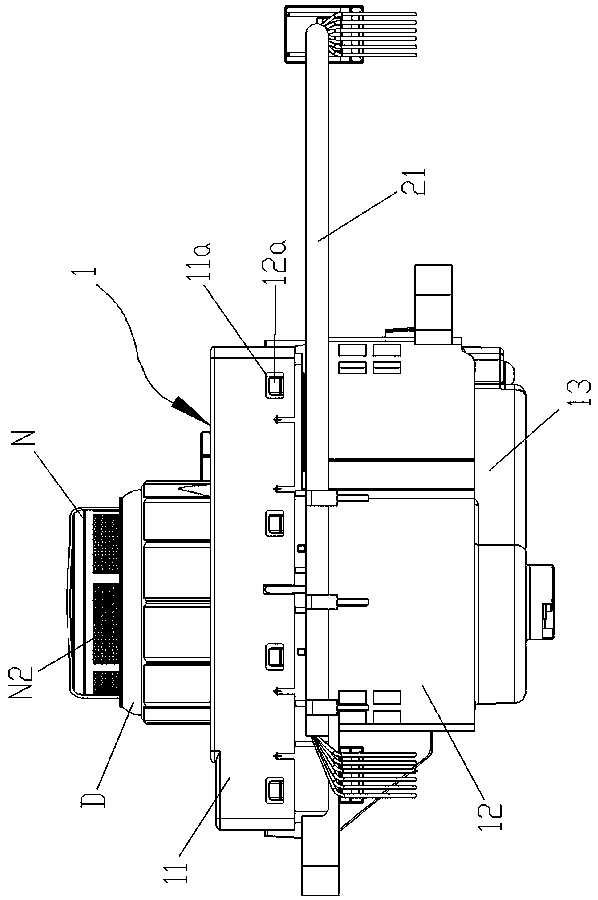
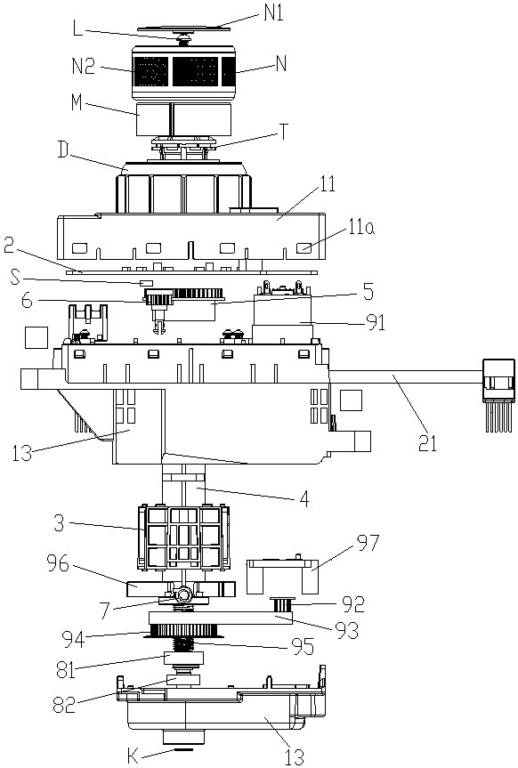
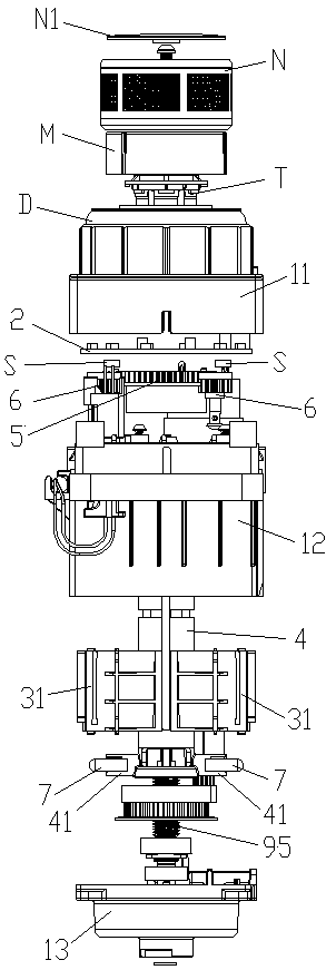
[0030] Figures 1 to 10 It is a structural representation of the present invention.

[0031] The reference signs are: light guide ring D, retaining spring K, knob screw L, inner cover M, knob N, knob cover N1, anti-skid pattern N2, magnet S, shrapnel cover T, shifter housing 1, upper housing 11. Buckle window 11a, middle shell 12, buckle head 12a, buckle cavity 12b, lower shell 13, buckle claw 13b, PCB board 2, wiring harness 21, curved surface block 3, guide chute 3a, return groove 3b, Gear slot 3c, soft rubber layer 3d, curved surface block unit 31, V-shaped opening cavity 32, limit block 33, positioning block 34, protrusion 35, lifting rod 4, hollow rod cavity 4a, gear pin assembly Hole 4b, guide rod hole 4c, guide cylinder 41, gear gear 5, signal gear 6, rotating shaft 61, anti-off chuck 62, elastic deformation gap 62a, gear pin 7, large ...


PUM


Abstract

The invention discloses an automatic lifting type electronic rotary knob gear shifter. The automatic lifting type electronic rotary knob gear shifter comprises a gear shifter shell provided with a rotary knob. The gear shifter shell is internally provided with a PCB, a curved face block and a lifting rod. The lower part of the lifting rod is provided with an electric lifting mechanism, and the electric lifting mechanism is connected with the PCB in a circuit control manner. The PCB is provided with a luminescent tube, and the rotary knob is sleeved with a light guide ring. A lifting rod is fixedly sleeved with a tap position gear, and the tap position gear is connected with signal gears in a drive manner. The rotary knob is fixedly installed at the upper end of the lifting rod, and according to the rotary knob, during gear shifting, the lifting rod can be manually rotated to drive the signal gear to generate so that angular displacement signals can be generated; the PCB is provided with a detecting component which can convert the angular displacement signals of the signal gears into gear shifting electric signals, and a wiring harness which is connected with the PCB and used for outputting the gear shifting electric signals is led out of the gear shifter shell. A spiral guiding slide groove plays a role in guiding and stabilizing spiral lifting of the lifting rod is machined inthe curved face block, and the lifting rod is provided with a tap position pin which makes elastic sliding contact with the guiding slide groove of the curved face block and can improve the gear shifting operation hand feeling.

Description

technical field [0001] The invention relates to an automobile shifting device, in particular to an automatic lifting electronic knob shifter assembly. Background technique [0002] As the shifting device of a car, the shifter is an important part of the vehicle. It can be divided into a mechanical shifter and an electronic shifter. The mechanical shifter completes the switching between each group of gears through a mechanical structure. The electronic shifter The stopper sends an electronic signal through the control device, and the electronic signal controls the actuator to complete the switching between the gears of each group. [0003] The mechanical shifting device has a complex structure and takes up a lot of space; and the use of an electronic shifter will improve the grade of the car, so more and more vehicle manufacturers switch to electronic shifters. Some existing electronic shifters The shift operation is controlled by buttons, and the shift command is sent by th...

Claims


Application Information

Patent Timeline
Patent Type & Authority Applications(China)
IPC IPC(8): F16H59/12F16H61/02
CPCF16H59/12F16H61/0204
Inventor 潘贻静
Owner 宁波德普隆汽车系统有限公司
Learn More