Solid-liquid separation mechanism for sewage treatment
A technology for sewage treatment and solid-liquid separation, which is applied in water/sewage treatment, multi-stage water/sewage treatment, water/sludge/sewage treatment, etc. It can solve the problems of easy accumulation of solid impurities and achieve good sealing and good Solid-liquid separation, the effect of ensuring sealing
- Summary
- Abstract
- Description
- Claims
- Application Information
AI Technical Summary
Problems solved by technology
Method used
Image
Examples
Embodiment 1
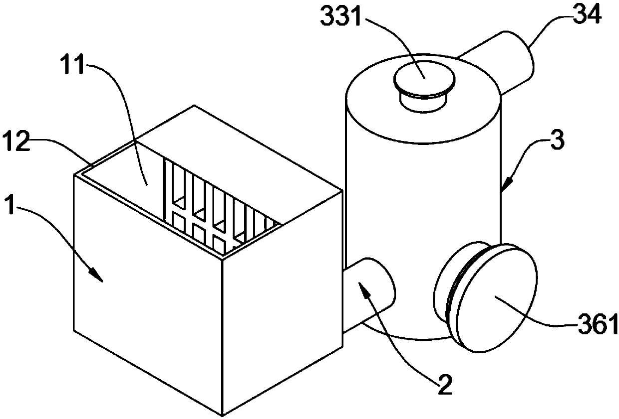
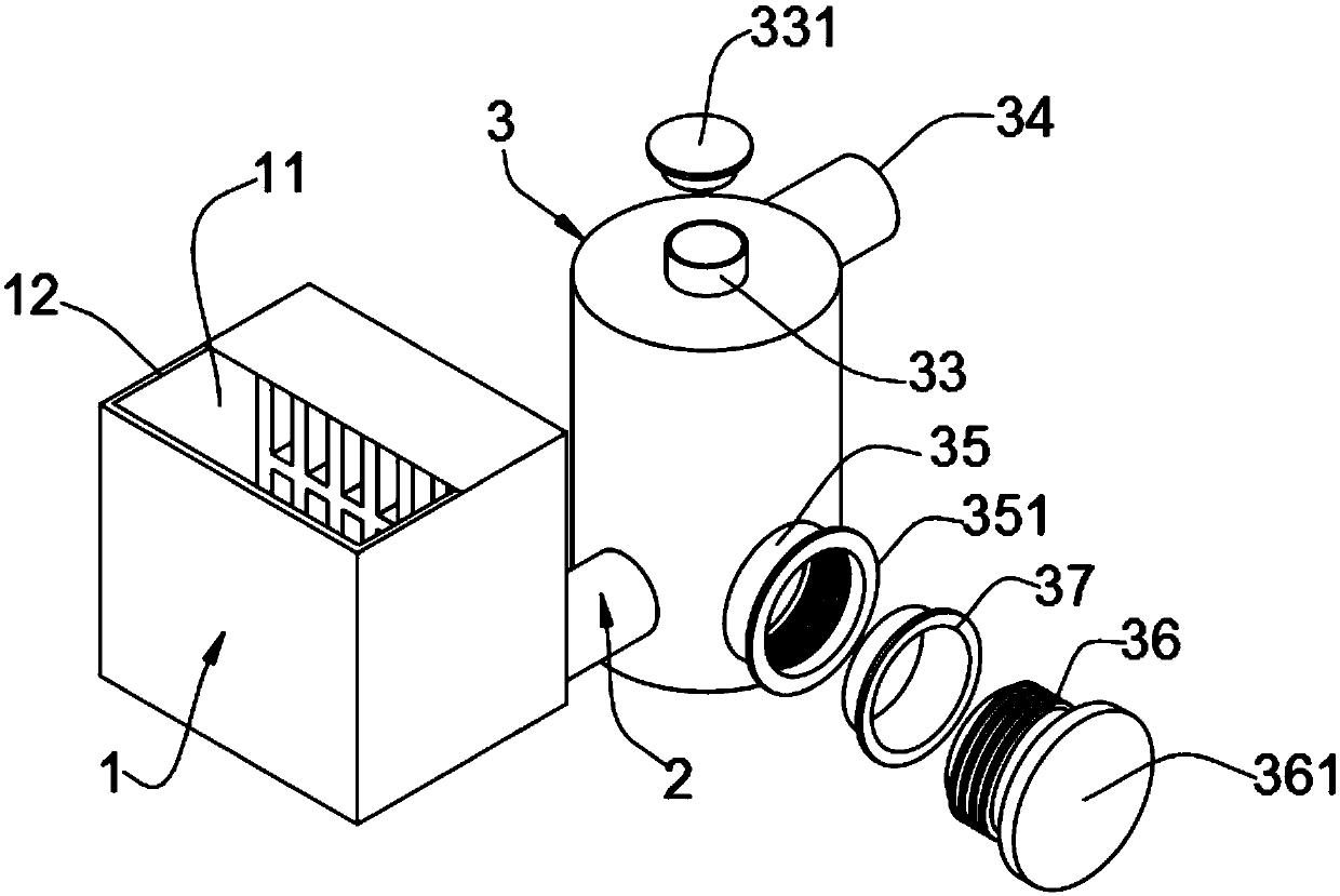
[0031] A solid-liquid separation mechanism for sewage treatment, such as figure 1 , figure 2 , Figure 4 with Figure 5 As shown, the sewage treatment tank 1 is included, the sewage treatment tank 1 is provided with a cavity 11, the top wall of the cavity 11 is provided with a water inlet tank 12, the sewage treatment tank 1 is provided with a connecting pipe 2, and the sewage treatment tank 1 is provided with There is a through hole for the connecting pipe 2 to pass through, and the connecting pipe 2 is tightly welded to the hole wall of the through hole in the sewage treatment tank 1. The end of the connecting pipe 2 is connected to a sewage filter cartridge 3, and the sewage filter cartridge 3 is equipped with a There is a through hole for the connecting pipe 2 to pass through, and the connecting pipe 2 and the hole wall of the through hole in the sewage filter cartridge 3 are tightly welded. The sewage filter cartridge 3 is provided with a filter chamber 31, and the cav...
Embodiment 2
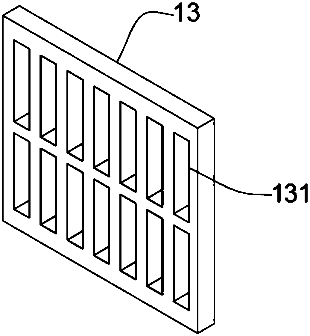
[0038] In the specific operation, since the sewage directly enters the sewage treatment tank 1, it is easy to cause the connecting pipe 2 to be blocked. Therefore, on the basis of the embodiment 1, the sewage treatment tank 1 is improved. As a preferred embodiment, as image 3 As shown, a blocking fence 13 is installed on the wall of the cavity 11, and the blocking fence 13 is tightly welded on the cavity wall of the cavity 11. On the blocking fence 13, there are two sets of upper and lower groups of rectangular shapes that are symmetrical to each other and arranged at linear equal intervals. Groove 131.
[0039] In this embodiment, by setting the blocking fence 13, and the blocking fence 13 is provided with a rectangular groove 131, the sewage can directly flow out through the rectangular groove 131, and the larger impurities are left on the blocking fence 13, which solves the general problem The problem that the pipes in the solid-liquid separation mechanism for sewage treat...
Embodiment 3
[0041] In specific operation, in order to further improve the solid-liquid separation effect in sewage, therefore, on the basis of embodiment 1, make improvement to sewage filter cartridge 3, as a kind of preferred embodiment, as Image 6 with Figure 7As shown, a fixed ring 321 is installed in the annular groove 32, and a through hole 3211 is provided in the fixed ring 321, and a coarse filter screen 322 is tightly bonded on the hole wall of the through hole 3211, and the upper surface of the coarse filter screen 322 is provided with a fine filter. Net 323, and the fine filter screen 323 is closely bonded on the groove wall of the annular groove 32.
[0042] Specifically, the horizontal plane where the connecting pipe 2 is located is located below the plane where the fixed ring 321 is located, and the horizontal plane where the outlet pipe 34 is located is located above the fine filter screen 323, so as to ensure that the sewage enters the filter chamber 31, and first passes ...
PUM
 Abstract
Description
Claims
Application Information
 - R&D Engineer
- R&D Manager
- IP Professional
- Industry Leading Data Capabilities
- Powerful AI technology
- Patent DNA Extraction
Browse by: Latest US Patents, China's latest patents, Technical Efficacy Thesaurus, Application Domain, Technology Topic, Popular Technical Reports.
© 2024 PatSnap. All rights reserved.Legal|Privacy policy|Modern Slavery Act Transparency Statement|Sitemap|About US| Contact US: help@patsnap.com


