
Auxiliary robot system for ophthalmic microsurgery

A robotic system and microsurgery technology, applied in surgical robots, surgical manipulators, etc., can solve the problems of poor surgical operation accuracy and stability, and achieve the effect of eliminating physiological tremor, improving accuracy and stability, and eliminating jitter.

Active Publication Date: 2019-04-12
HARBIN INST OF TECH
View PDF6 Cites 5 Cited by
  • Summary
  • Abstract
  • Description
  • Claims
  • Application Information

AI Technical Summary

Problems solved by technology

[0004] The purpose of the present invention is to solve the problem of poor accuracy and stability of surgical operation when the existing surgical instruments need to penetrate the patient's eyeball from the sclera puncture point

Method used


Image

  • Auxiliary robot system for ophthalmic microsurgery
  • Auxiliary robot system for ophthalmic microsurgery
  • Auxiliary robot system for ophthalmic microsurgery

Examples


specific Embodiment approach 1

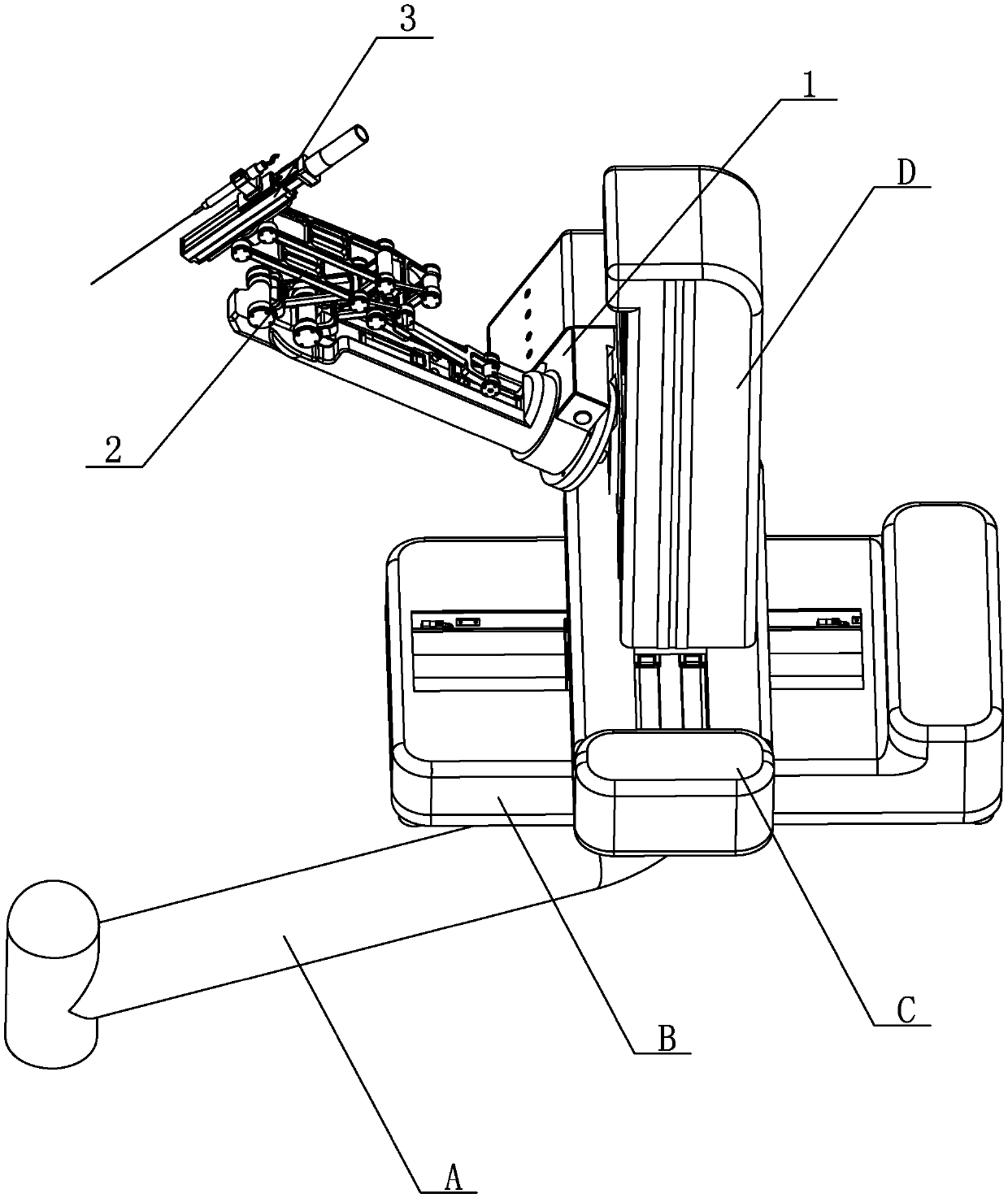
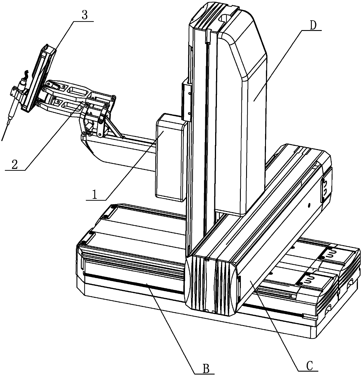
[0016] Specific implementation mode one: combine Figure 1 to Figure 7 Describe this embodiment, a kind of ophthalmic microsurgery auxiliary robot system of this embodiment, it comprises main operating table 6, and main operating table 6 is installed on the workbench, is characterized in that: it also comprises 3D video microscope device 7, The dual-arm robot 8 and the foot switch 9, the main operating table 6 is located between the dual-arm robots 8, and the lower part of the main operating table 6 is connected to the base of the dual-arm robot 8 as a whole, and the 3D video microscope device 7 is hoisted above the middle part of the double manipulator robot 8, and the foot switch 9 is connected to the 3D video microscope device 7 and the double manipulator robot 8 through a flexible cable and drag chain;

[0017] The double manipulator robot 8 includes a main manipulator and a secondary manipulator, and the main manipulator and the secondary manipulator are arranged symmetri...

specific Embodiment approach 2

[0033] Specific implementation mode two: combination Figure 4 Describe this embodiment, the rotating module 1-1 of this embodiment comprises motor, transmission device, worm and worm wheel, the output end of motor is connected with transmission device, the output end of transmission device is connected with worm wheel, and worm screw is installed on the cantilever 1-3 Inside, and the worm meshes with the worm gear. In actual use, the manufacturer of the rotation module 1-1 is R150M produced by Parker. Such arrangement drives the rotation of the entire cantilever 1-3 around the cantilever axis; the connection method is simple and reliable, and other components and connection relations are the same as those in the first embodiment.

specific Embodiment approach 3

[0034] Specific implementation mode three: combination figure 1 To describe this embodiment, the model of the cantilever linear guide module 1-4 in this embodiment is KK40-01P-150A-F2ES2 (PNP). With such arrangement, the stroke is large, the production is convenient, and the cost is low. Other compositions and connections are the same as those in Embodiment 1 or 2.


PUM


Abstract

The invention relates to an auxiliary robot system for ophthalmic microsurgery, and relates to a dual-arm robot system. The present invention aims to solve the problem of poor accuracy and stability of the surgical operation of surgical instruments in the prior art. The system includes a main operating table (6), the main operating table (6) is mounted on a workbench, the system also includes a 3Dvideo microscopic device (7), dual-motion arm robots (8) and a foot switch (9), the main operating table (6) is located between the dual-motion arm robots (8), the lower part of the main operating table (6) is integrated with the base of the dual-motion arm robots (8), the 3D video microscopic device (7) is hoisted above the intermediate portion of the dual-motion arm robots (8), and the foot switch (9) is connected to the 3D video microscopic device (7) and the dual-motion arm robots (8) via flexible cables and drag chains. The system is used for fundus microsurgery.

Description

technical field [0001] The invention relates to a dual-arm robot system, in particular to an ophthalmic microsurgery auxiliary robot system. Background technique [0002] Due to the small size of the eyeball and the delicate and fragile structure of the eyeball tissue, ophthalmic microsurgery requires doctors to have extremely high hand-eye coordination. In traditional ophthalmic microsurgery, the operator completes the corresponding delicate operations under the microscope by holding ophthalmic instruments. Due to the long operation time, the operator is prone to physiological trembling of the hand, which makes the success rate of the operation low; among them , Once there is a mistake in the operation of the fine structures of the tissues in the eyeball, such as the posterior lens capsule, corneal endothelium, zonular ligament, macular area, etc., it will cause irreparable iatrogenic damage to the patient's vision. The particularity of ophthalmic microsurgery also makes t...

Claims


Application Information

Patent Timeline
Patent Type & Authority Applications(China)
IPC IPC(8): A61B34/37
CPCA61B34/37A61B34/70
Inventor 张赫廖一博赵杰
Owner HARBIN INST OF TECH
Learn More