
Direct-current charging pile dynamic intelligent power distribution system and distribution method

An intelligent power, DC charging technology, applied in charging stations, electric vehicles, electric vehicle charging technology, etc., can solve problems such as waste, achieve the effect of reducing waste and realizing power distribution

Inactive Publication Date: 2019-04-09
JIANGSU WANBANG DEHE NEW ENERGY TECH CO LTD
View PDF6 Cites 1 Cited by
  • Summary
  • Abstract
  • Description
  • Claims
  • Application Information

AI Technical Summary

Problems solved by technology

[0002] At present, the charging pile adopts the module combination method, and when the demand of the vehicle terminal does not reach the full load power of the charging pile, there is a lot of waste; therefore, it is necessary to make reasonable use of the waste of the module to meet the high-power charging of a few terminals and the low-power charging of multiple terminals. need

Method used


Image

  • Direct-current charging pile dynamic intelligent power distribution system and distribution method
  • Direct-current charging pile dynamic intelligent power distribution system and distribution method
  • Direct-current charging pile dynamic intelligent power distribution system and distribution method

Examples


Embodiment 1

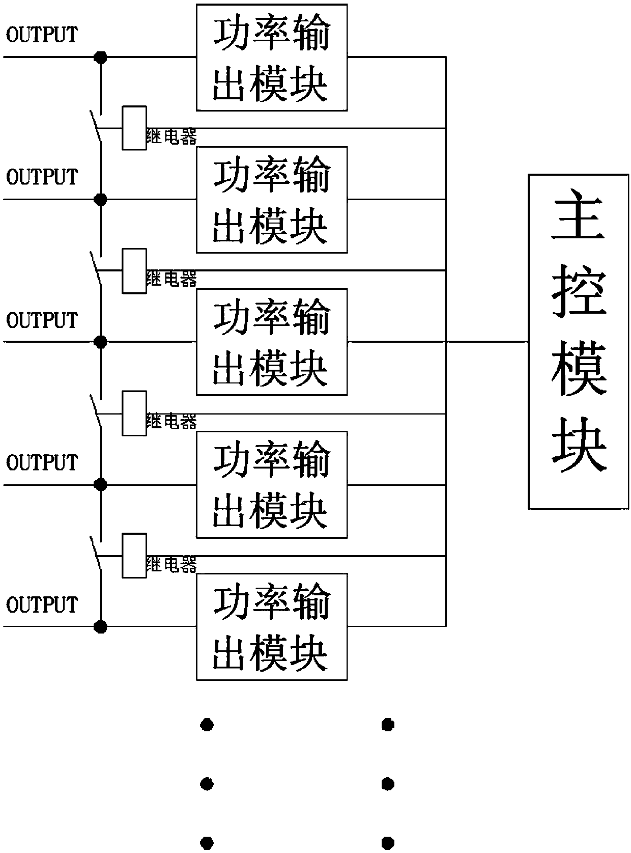
[0037] figure 1 It is a system block diagram of the DC charging stack dynamic intelligent power distribution system involved in the present invention.

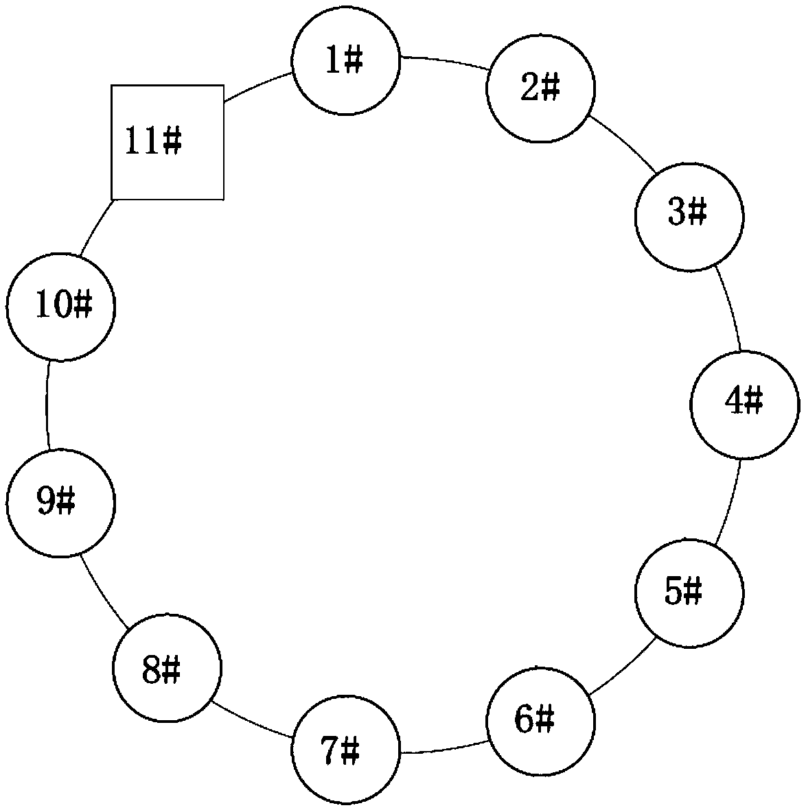
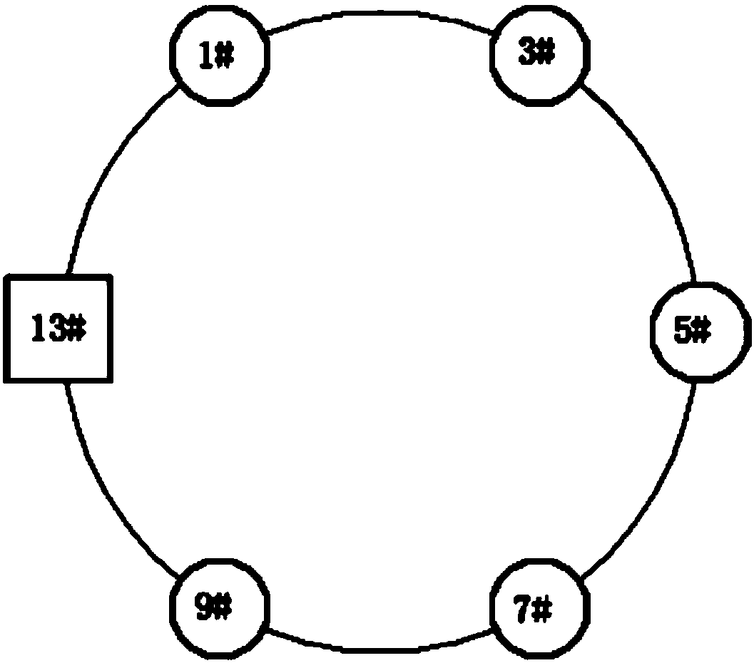
[0038] Such as figure 1 As shown, this embodiment provides a dynamic intelligent power distribution system for DC charging piles, including: a main control module, and several power output modules controlled by the main control module; the main control module can be but not limited to adopt MY - EVC6200 main control board; wherein each power output module is grouped to form several power distribution rings; the power output module can be but not limited to adopt 10 power output modules of 30kW, and divide the 10 power output modules into two power distribution ring; when a power distribution ring needs to output power, the main control module is suitable for controlling the combination of each power output module in the power distribution ring to adapt to the required output power; by adapting the required output power, the p...

Embodiment 2

[0047] Figure 5 It is a schematic diagram of the working method of the DC charging pile dynamic intelligent power distribution system involved in the present invention.

[0048] Such as Figure 5 As shown, on the basis of Embodiment 1, Embodiment 2 also provides a dynamic intelligent power distribution method for DC charging piles, including: each power output module is grouped to form several power distribution rings to achieve single-ring distribution, that is, in a When the power distribution ring needs to output power, the main control module controls the combination of power output modules in the power distribution ring to adapt to the required output power; that is, the full output power of the charging gun can be but not limited to 90kW, when a power distribution ring When there is a charging gun inside, the main control module can control the 3 power output modules in the power distribution ring to adapt to the full power of the charging gun.

[0049] In this embodi...


PUM


Abstract

The invention relates to the field of charging piles, in particular to a direct-current charging pile dynamic intelligent power distribution system and distribution method. The direct-current chargingpile dynamic intelligent power distribution system comprises a master control module and multiple power output modules controlled by the master control module; the power output modules are grouped toform multiple power distribution rings, when one power distribution ring needs to output power, the master control module is suitable for controlling the power output modules in the power distribution rings to be combined to be matched with needed output power, the dynamic power distribution of a charging pile is achieved, and power waste is reduced.

Description

technical field [0001] The invention relates to the field of charging piles, in particular to a DC charging pile dynamic intelligent power distribution system and a distribution method thereof. Background technique [0002] At present, the charging pile adopts the module combination method, and when the demand of the vehicle terminal does not reach the full load power of the charging pile, there is a lot of waste; therefore, it is necessary to make reasonable use of the waste of the module to meet the high-power charging of a few terminals and the low-power charging of multiple terminals. need. [0003] Based on the above problems, it is necessary to design a new DC charging stack dynamic intelligent power distribution system and its distribution method. Contents of the invention [0004] The purpose of the present invention is to provide a DC charging pile dynamic intelligent power distribution system and a distribution method thereof. [0005] In order to solve the abo...

Claims


Application Information

Patent Timeline
IPC IPC(8): B60L53/60B60L53/66
CPCY02T90/16Y02T10/7072Y02T10/70Y02T90/12
Inventor 班逸邵丹薇李德胜储丹杨志
Owner JIANGSU WANBANG DEHE NEW ENERGY TECH CO LTD
Learn More