A tri-gate component and an ion source containing the tri-gate component

A component and inner grid technology, applied in the field of low-energy and wide-beam extraction conditions, can solve problems such as increased equipment costs, grid deformation, and complex structures, and achieve the effects of reducing equipment manufacturing costs, reducing size, and avoiding deformation and short circuits

Active Publication Date: 2020-08-28
48TH RES INST OF CHINA ELECTRONICS TECH GROUP CORP
View PDF8 Cites 0 Cited by
  • Summary
  • Abstract
  • Description
  • Claims
  • Application Information

AI Technical Summary

Problems solved by technology

However, since the distance between the grids is very short (less than 2mm), and the inner grid is at the exit of the plasma, the temperature is high, which can easily lead to grid deformation and short circuit. In order to solve this problem, the conventional method is to increase the Increase the size of the three grids and increase the strength of the grid by adding parts on the outer periphery of the grid. Although this is beneficial to prevent the deformation of the grid, it will lead to a complex structure and a large increase in size. Further, the size of the reaction chamber also needs to be increased accordingly. Large, resulting in greatly increased equipment costs

Method used


Image

  • A tri-gate component and an ion source containing the tri-gate component
  • A tri-gate component and an ion source containing the tri-gate component
  • A tri-gate component and an ion source containing the tri-gate component

Examples


Embodiment 1

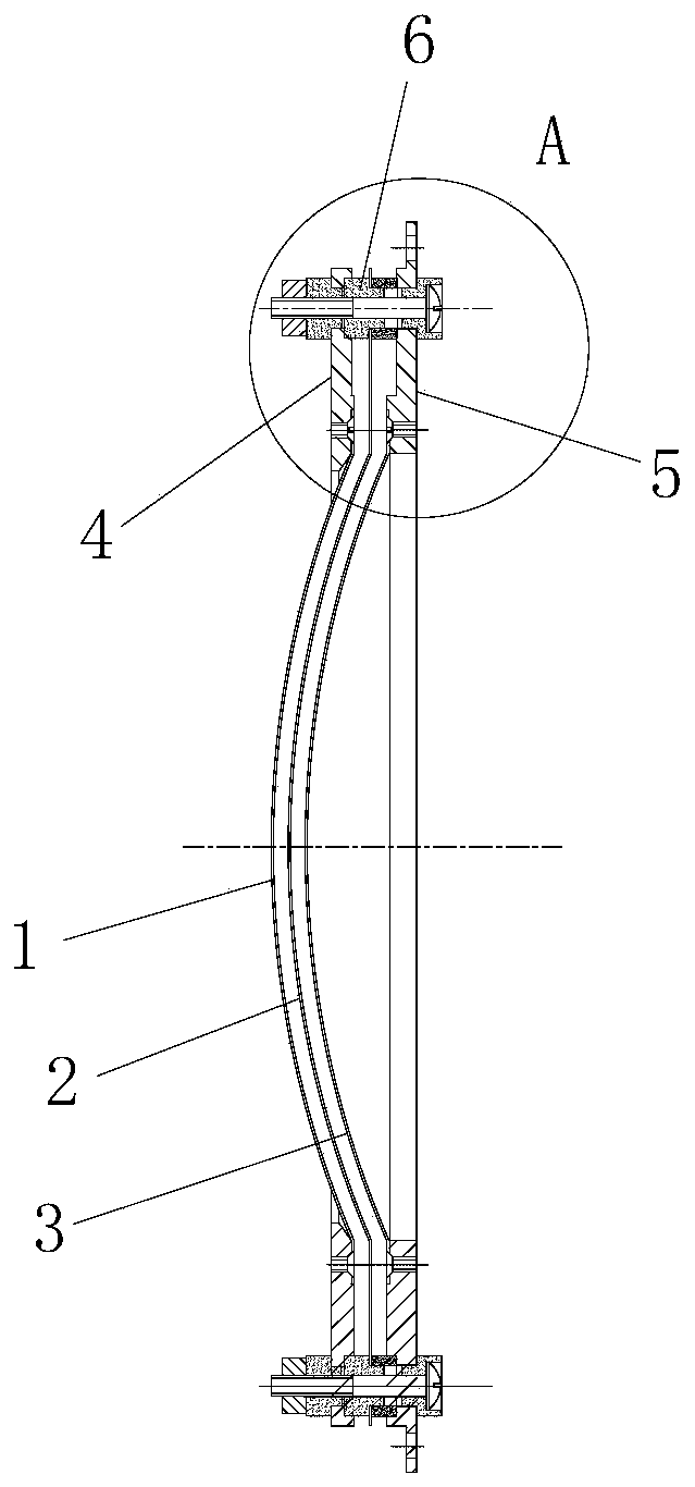
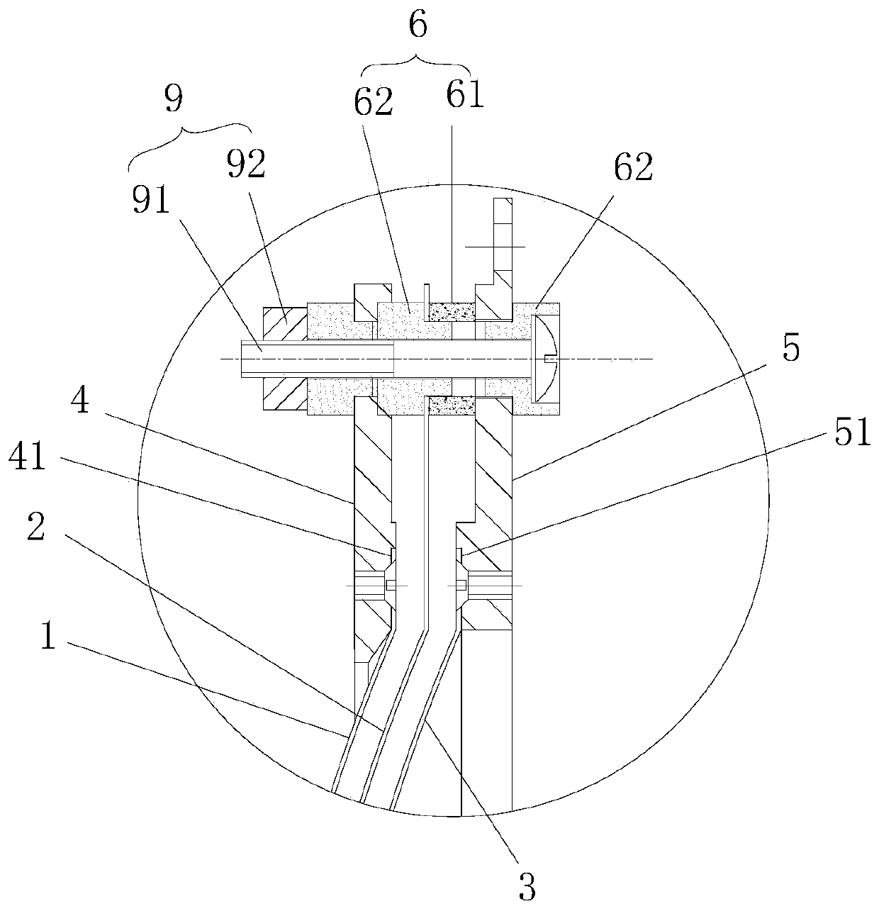
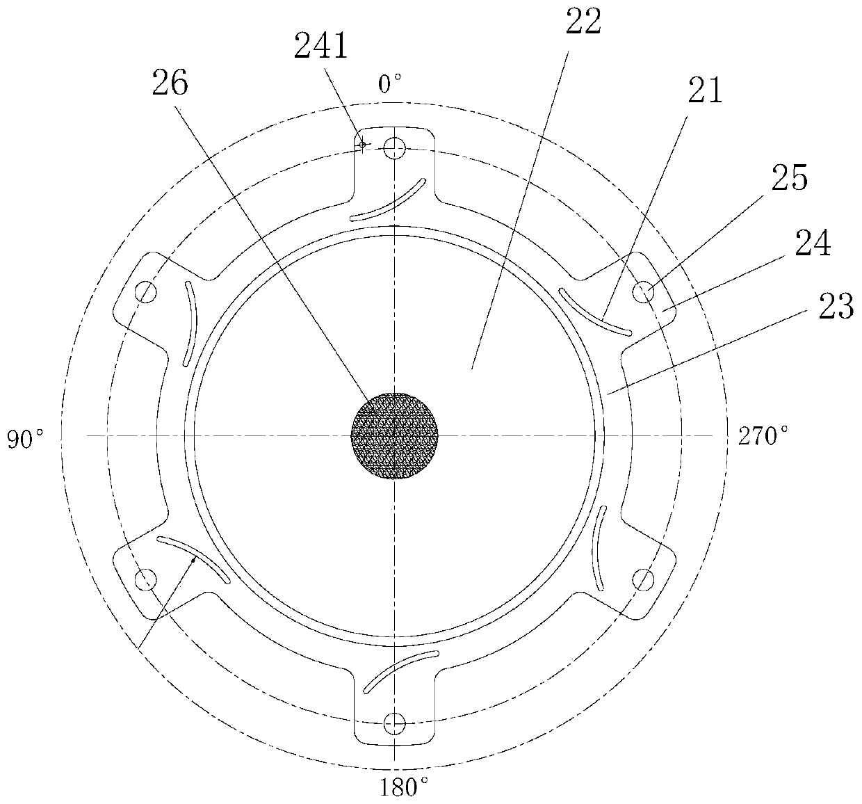
[0025] Figure 1 to Figure 3 An embodiment of the three-grid assembly of the present invention is shown. The three-grid assembly of the present embodiment includes an inner grid 1, a middle grid 2 and an outer grid 3 arranged in parallel in sequence, and the inside of the inner grid 1 (accompanying drawing) The left side in the middle) is provided with an inner flange 4, the inner grid 1 is installed on the inner flange 4, and the outer grid 3 (right side in the drawing) is provided with an outer flange 5, and the outer grid 3 is installed on the On the outer flange 5, between the inner flange 4 and the middle grid 2, and between the outer flange 5 and the middle grid 2, insulating spacers 6 are sandwiched, and the insulation spacers 6 are used to connect the gaps between the grids. Insulated and isolated, the grid 2 is provided with a stress absorbing groove 21 for absorbing thermal deformation. Preferably, the insulating spacer 6 can be a combination of a T-shaped insulatin...

Embodiment 2

[0033] Figure 4 An embodiment of the ion source of the present invention is shown. The ion source of this embodiment includes an inner cover 7, a discharge chamber 8 located inside the inner cover 7, and an anode 10 and a cathode 20 located in the discharge chamber 8, and also includes In the above-mentioned three-bar assembly, the inner flange 4 in the three-bar assembly is in close contact with the discharge chamber 8 to ensure that the inner grid 1 is at a high potential during operation, and the outer flange 5 in the three-bar assembly is connected to the inner cover 7 to ensure that the working , the outer flange 5 and the inner cover 7 are at ground potential.

[0034] The ion source of the present invention contains the above-mentioned tri-grid assembly, so it also has the above-mentioned advantages.


PUM


Abstract

The invention discloses a three-grid assembly. The three-grid assembly comprises an inner grid, a middle grid and an outer grid which are parallelly arranged in sequence; the inner side of the inner grid is provided with an inner flange, and the inner grid is installed on the inner flange; the outer side of the outer grid is provided with an outer flange, and the outer grid is installed on the outer flange; insulated isolation pieces are arranged between the inner flange and the middle grid as well as between the outer flange and the middle grid in a clamping mode; and the middle grid is provided with stress absorption grooves used for absorbing thermal deformation. The invention further discloses an ion source. The ion source comprises an inner cover, a discharge chamber located in the inner cover, a cathode and an anode, and the cathode and the anode are located in the discharge chamber. The ion source further comprises the three-grid assembly, the inner flange in the three-grid assembly is closely attached to the discharge chamber, and the outer flange in the three-grid assembly is connected with the inner cover. The three-grid assembly and the ion source comprising the same have the advantages that the structure is simple, the cost is low, the distance between the grids is decreased advantageously, and the grids are prevented from deformation and short circuit.

Description

technical field [0001] The invention relates to ion beam sputtering coating equipment, in particular to a three-grid assembly and an ion source containing the three-grid assembly, which is especially suitable for low-energy and wide-beam extraction working conditions. Background technique [0002] Ion beam sputtering is one of the physical sputtering methods. As a new generation of thin film growth method, it has the characteristics of pure film material, high film density and strong adhesion, and has been widely used in semiconductor, thin film materials, optical components and other industries. [0003] Thin film deposition is divided into physical deposition and chemical deposition. Physical deposition is a purely physical action, which does not change the atomic structure and composition of the target and the deposited material. Just transfer the target material to the workpiece according to the same composition ratio and atomic (or molecular) structure. There are thr...

Claims


Application Information

Patent Timeline
Patent Type & Authority Patents(China)
IPC IPC(8): C23C14/46
CPCC23C14/46
Inventor 陈特超
Owner 48TH RES INST OF CHINA ELECTRONICS TECH GROUP CORP
Why Eureka
Try Eureka