
Battery with indication function

A technology of indication and function, applied in the field of batteries with indication function, can solve the problems of inoperability and low accuracy, and achieve the effect of avoiding power running

Active Publication Date: 2019-03-29
JIAN CRAB KINGDOM TECH CO LTD
View PDF17 Cites 5 Cited by
  • Summary
  • Abstract
  • Description
  • Claims
  • Application Information

AI Technical Summary

Problems solved by technology

[0002] The battery is an energy storage element that is used in every household. It is small in size and easy to use. A small dry battery is used in remote controls, toys, etc. After understanding, it leads to inoperable situation during use. After searching the Chinese patent number: CN105591167B energy-concentrating indicating battery, by setting the indicating liquid in the battery, it can be an electrorheological fluid or an organic color-changing liquid. According to the usage of the power, the The state of the electrorheological fluid changes, and the color of the latter organic color-changing liquid changes to estimate the battery power, but the estimation accuracy is low; in addition, after searching the Chinese patent number: CN104701480B anti-leakage battery, the application document In this method, a conductive liquid is set in the sealed cavity, and under the action of the gravity of the conductive liquid, the conductive liquid moves at both ends of the sealed cavity, so that when it moves to one end with a conductive contact piece, the battery is energized, and at the other end, it is realized. Power off, but because it is a conductive liquid, it will inevitably adhere to the inner wall of the sealed cavity when moving, and there is a possibility of conducting the battery

Method used


Image

  • Battery with indication function
  • Battery with indication function
  • Battery with indication function

Examples


Embodiment Construction

[0017] The following will clearly and completely describe the technical solutions in the embodiments of the present invention with reference to the accompanying drawings in the embodiments of the present invention. Obviously, the described embodiments are only some, not all, embodiments of the present invention.

[0018] In describing the present invention, it should be understood that the terms "upper", "lower", "front", "rear", "left", "right", "top", "bottom", "inner", " The orientation or positional relationship indicated by "outside", etc. is based on the orientation or positional relationship shown in the drawings, and is only for the convenience of describing the present invention and simplifying the description, rather than indicating or implying that the referred device or element must have a specific orientation, so as to Specific orientation configurations and operations, therefore, are not to be construed as limitations on the invention.

[0019] refer to Figure ...


PUM


Abstract

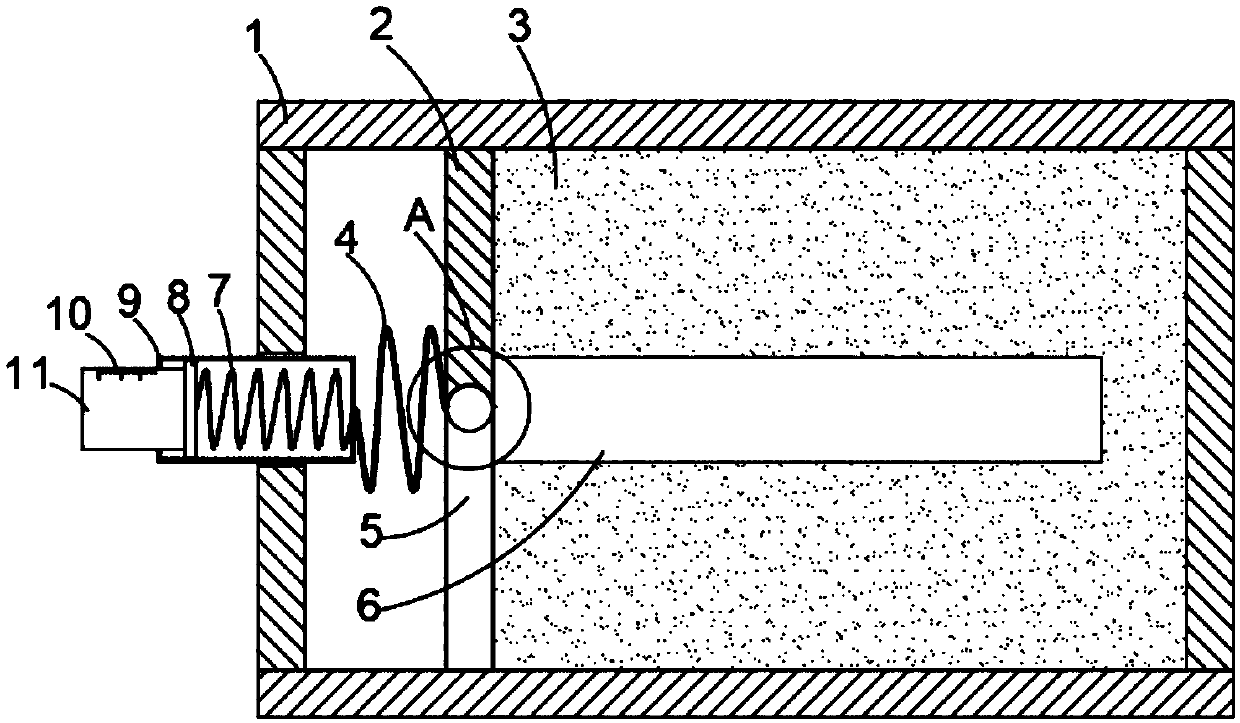
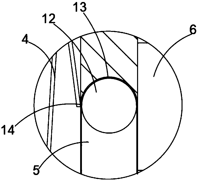
The invention discloses a battery with an indication function. The battery comprises a housing, a negative plate, an electrolyte, a cell and a positive electrode terminal. The interior of the housingis divided into two cavities through a liquid sealing plate. The electrolyte is located in the cavity close to one side of the negative plate, and a transversely arranged conductive spring is arrangedin the other cavity. One end of the conductive spring makes contact with the cell, and the other end of the conductive spring is connected with a transversely arranged positive pole, wherein the positive pole is of a hollow structure, and the positive pole is connected with the positive electrode terminal through the transversely arranged spring. The positive electrode terminal is inserted into the positive pole and is in sliding connection with the positive pole. A conductive layer is arranged on the inner wall of the positive pole, a conductive sliding block is fixedly connected to the sidewall of the outer side of the positive electrode terminal, and the conductive sliding block makes contact with the conductive layer. According to the invention, the battery with the indication function can achieve the accurate indication of the use amount of the battery, and can effectively avoid an electric leakage phenomenon when the battery is not used.

Description

technical field [0001] The invention relates to the technical field of energy storage components, in particular to a battery with an indicating function. Background technique [0002] The battery is an energy storage element that is used in every household. It is small in size and easy to use. A small dry battery is used in remote controls, toys, etc. After understanding, it leads to inoperable situation during use. After searching the Chinese patent number: CN105591167B energy-concentrating indicating battery, by setting the indicating liquid in the battery, it can be an electrorheological fluid or an organic color-changing liquid. According to the usage of the power, the The state of the electrorheological fluid changes, and the color of the latter organic color-changing liquid changes to estimate the battery power, but the estimation accuracy is low; in addition, after searching the Chinese patent number: CN104701480B anti-leakage battery, the application document In thi...

Claims


Application Information

Patent Timeline
Patent Type & Authority Applications(China)
IPC IPC(8): H01M6/50
CPCH01M6/5044
Inventor 桂美苹
Owner JIAN CRAB KINGDOM TECH CO LTD
Learn More