
A motor stator and rotor assembly device

A stator-rotor and rotor technology, which is applied in the field of motor stator-rotor assembly devices, can solve the problems of small external guide hole diameter, inability to ensure accurate centering and positioning, and inability to determine and so on.

Active Publication Date: 2019-08-09
CSR ZHUZHOU ELECTRIC CO LTD
View PDF7 Cites 1 Cited by
  • Summary
  • Abstract
  • Description
  • Claims
  • Application Information

AI Technical Summary

Problems solved by technology

[0005] 1. The texture of PTFE is relatively soft, which cannot guarantee accurate centering and positioning, and the rotor will be subjected to a magnetic pull biased to one side, which is unfavorable for assembly
[0006] 2. Generally, the diameter of the external guide hole is small, and the design of the guide tooling cannot determine the position of the rotor due to mutual attraction during the assembly process, which cannot be accurately guided and adjusted.
[0007] 3. For the combination of stator and rotor with compact motor structure, one-sided weight of the rotor and in a narrow assembly space, the existing assembly technology cannot meet the alignment requirements
[0008] 4. The original co-packing technical solution has insufficient operability and low efficiency, which is unfavorable for mass production

Method used


Image

  • A motor stator and rotor assembly device

Examples


Embodiment Construction

[0028] In order to make the purpose, technical solutions and advantages of the embodiments of the present invention clearer, the technical solutions in the embodiments of the present invention will be clearly and completely described below in conjunction with the drawings in the embodiments of the present invention. Obviously, the described embodiments It is a part of embodiments of the present invention, but not all embodiments. Based on the embodiments of the present invention, all other embodiments obtained by persons of ordinary skill in the art without making creative efforts belong to the protection scope of the present invention.

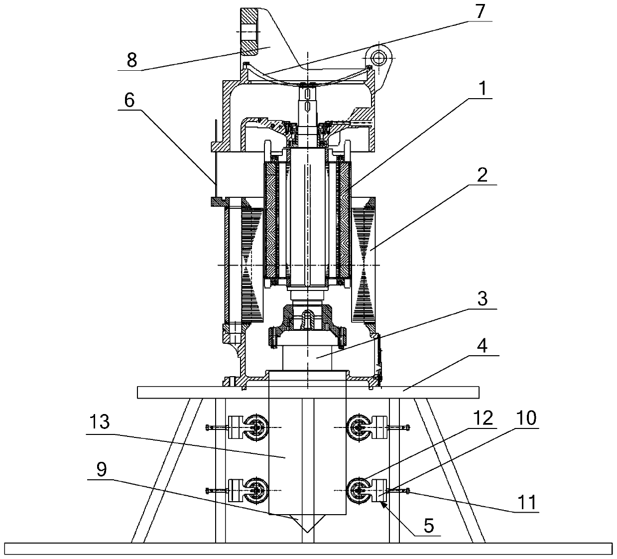
[0029] Please refer to figure 1 , figure 1 It is a schematic structural diagram of a motor stator-rotor assembly device provided by an embodiment of the present invention.

[0030] The motor stator-rotor assembly device provided by the embodiment of the present invention includes a bracket, a taper tooling 3 and an adjustment device 5. The ...


PUM


Abstract

The invention discloses a motor stator-rotor assembling device. The motor stator-rotor assembling device comprises a bracket, a tapered tool and an adjusting device, wherein the bracket comprises a frame body and a mounting plate fixed on the frame body; the tapered tool comprises a guide post, and a first conical block and a second conical block which are matched with each other through conical surfaces; the adjusting device comprises an adjusting block and a threaded rod; a stator of a motor is fixed on the mounting plate; the first conical block is used for being fixed on an end face of a revolving shaft at one end of a rotor of the motor; the second conical block is fixed on the guide post; the mounting plate is provided with a through hole being in alignment with a rotor mounting position inside the stator; the guide post passes through the through hole; the adjusting device is arranged on the frame body, positioned below the mounting plate, and used for adjusting the obliqueness of the guide post; the adjusting block is in a threaded connection with the threaded rod; the adjusting block is in contact with a side wall of the guide post; and the threaded rod is in a threaded connection with the frame body. Through adoption of the motor stator-rotor assembling device provided by the invention, stable centering is realized in a stator-rotor assembling process, and attraction between the stator and the rotor is reduced.

Description

technical field [0001] The invention relates to the technical field of motor assembly, in particular to a motor stator and rotor assembly device. Background technique [0002] Due to its high power factor and high efficiency, permanent magnet motors have gradually replaced the most commonly used AC asynchronous motors in many occasions. The difficulty in the assembly of the stator and rotor of a permanent magnet motor is that there are permanent magnets in the rotor, which will generate an adsorption force on the stator. Especially when the motor has a slender structure, it is extremely difficult to assemble the stator and rotor to prevent mutual attraction. If the stator and rotor are eccentric during the assembly process, the two will attract and rub against each other, and the stator and rotor assembly cannot be completed. [0003] The existing method is to select a certain polytetrafluoroethylene as the air gap guide tool and place it between the stator and rotor accord...

Claims


Application Information

Patent Timeline
Patent Type & Authority Patents(China)
IPC IPC(8): H02K15/02
CPCH02K15/02
Inventor 姚秋华刘权黄志强宋悠全
Owner CSR ZHUZHOU ELECTRIC CO LTD
Learn More