
Roadside lighting device

A technology for lighting devices and lighting lamps, which is applied in the direction of lighting devices, fixed lighting devices, lighting device components, etc., can solve problems such as large power consumption, waste of electric energy, and troublesome laying of wires, and achieve reasonable use of electric energy and reduce cost, the effect of avoiding laying lines

Inactive Publication Date: 2019-03-29
高勇
View PDF0 Cites 1 Cited by
  • Summary
  • Abstract
  • Description
  • Claims
  • Application Information

AI Technical Summary

Problems solved by technology

[0002] At present, the light source on the road mainly adopts the introduction of external power supply to realize lighting. Because the road route is long and even in the wild environment, it is troublesome to lay the wires, resulting in high cost.
On th

Method used


Image

  • Roadside lighting device
  • Roadside lighting device

Examples


Example Embodiment

[0020] Example 1:

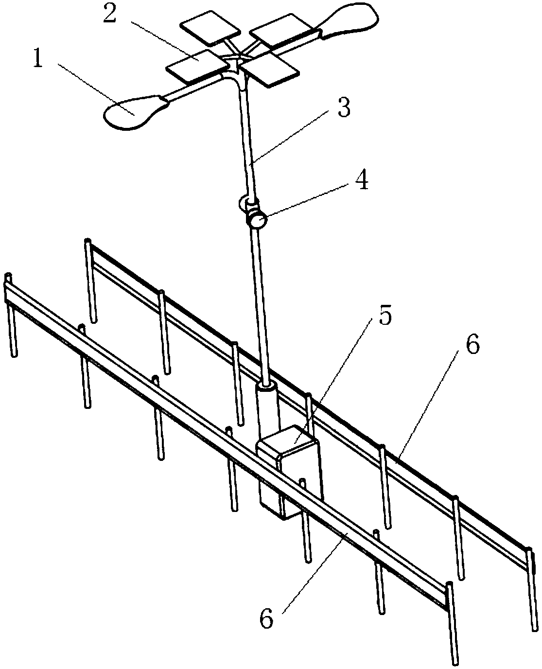
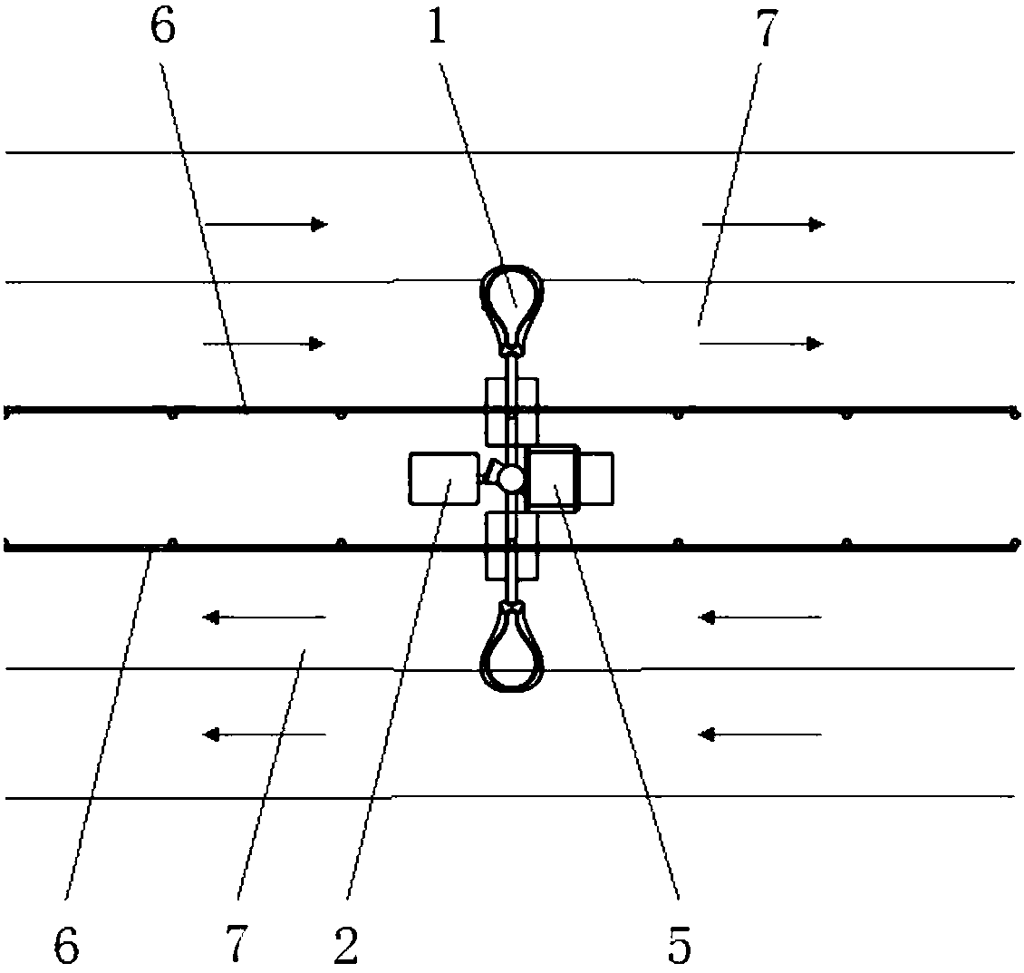
[0021] Such as figure 1 with figure 2 As shown, a roadside lighting device includes a lighting lamp 1 and a power supply. The lighting device also includes a light sensor 4 and a controller 5. The lighting lamp 1 is placed on the top of the vertical straight rod 3 and in the middle of the vertical straight rod 3. A light sensor 4 is installed in the upper position. The controller 5 is placed on the inside of the roadside fence 6 next to the vertical straight rod 3. The light sensor 4 is used to sense the intensity of the surrounding light and transmit the measured light information to the control The controller 5 controls the lighting lamp 1 to turn on or off according to the information measured by the light sensor 4. The top of the vertical straight rod 3 is also provided with a solar panel 2, and the electric energy generated by the solar panel 2 is transferred to the storage battery through the controller 5 for storage. The storage battery here is the ab...


PUM


Abstract

The invention discloses a roadside lighting device. The roadside lighting device includes a floodlight, a power supply, a light sensor and a controller, wherein the floodlight is arranged at the top of a vertically-straight rod; the light sensor is arranged at the position of the upper middle section of the vertically-straight rod; the controller is arranged on the inner side of a roadside fence next to the vertically-straight rod; the light sensor is used to sense the intensity of ambient light and transmits the measured light information to the controller; and the controller controls the floodlight to be turned on or off based on information measured by the light sensor. By the adoption of novel solar energy to provide electric energy, long-distance laying of the lines is avoided; the cost is greatly reduced; the roadside lighting device is further provided with a lighting control system for properly controlling the switching timing of the floodlight so that the use of the electric energy can be more reasonable; and the roadside lighting device has simple structure, outstanding practicability and great economic and social value.

Description

technical field [0001] The invention relates to a roadside lighting device, which belongs to the technical field of road lighting. Background technique [0002] At present, the light source on the road is mainly realized by introducing an external power source. Because the road is long and even in the wild environment, it is troublesome to lay the wires, resulting in high cost. On the other hand, the lamps in the existing roadside lighting devices are all arranged at a height of 4 to 5 meters, and high-power lamps are needed to illuminate the road surface, which consumes a lot of power and causes a large amount of waste of electric energy in vain. Contents of the invention [0003] The purpose of the present invention is to provide a new type of roadside lighting device for the above-mentioned shortcomings of the existing roadside lighting technology. The cost is reduced. At the same time, the device is also equipped with a lighting control system to reasonably control th...

Claims


Application Information

Patent Timeline
IPC IPC(8): F21S9/03F21V23/04F21V9/40F21W131/103
CPCF21S8/086F21S9/035F21V23/0464F21W2131/103Y02B20/72
Inventor 高勇
Owner 高勇
Learn More