
A Pile Length Detection Method Based on Zero Offset Method

A technology with zero offset distance and detection method, which is applied in the direction of foundation structure test, measurement device, foundation structure engineering, etc., can solve the problems such as inability to collect data at the pile end, limited space for data collection, and restricting the development of observation methods, etc. Achieve the effect of short detection time, strong practicability and wide application range

Active Publication Date: 2020-11-03
CHINA RAILWAY SIYUAN SURVEY & DESIGN GRP
View PDF4 Cites 0 Cited by
  • Summary
  • Abstract
  • Description
  • Claims
  • Application Information

AI Technical Summary

Problems solved by technology

However, on the one hand, due to the requirement that the data collection location is limited to the pile tip, the space for data collection is limited, which limits the development of its observation method; on the other hand, with the construction and development of various projects, more and more piles The pile length needs to be detected after the engineering inspection, and the pile end cannot be used for data collection. In this case, the application of the low-strain method is limited; in addition, the speed used in the calculation of the pile length by the low-strain method is an empirical value, not Detect the actual velocity value of the pile body, and the error of the detection result is relatively large

Method used


Image

  • A Pile Length Detection Method Based on Zero Offset Method
  • A Pile Length Detection Method Based on Zero Offset Method
  • A Pile Length Detection Method Based on Zero Offset Method

Examples


Embodiment Construction

[0026] The present invention will be further described in detail below in conjunction with the accompanying drawings and specific embodiments.

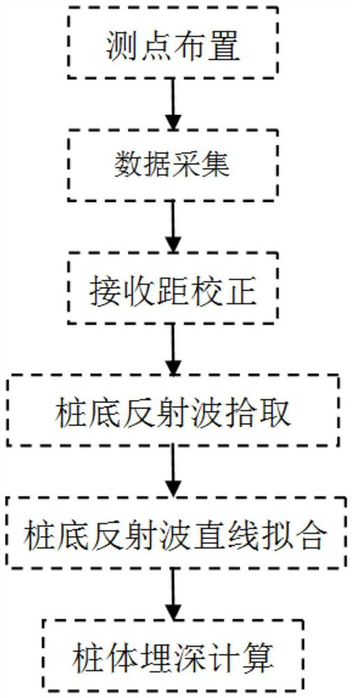
[0027] Such as figure 1 Shown is a pile length detection method based on the zero offset method, comprising the following steps:

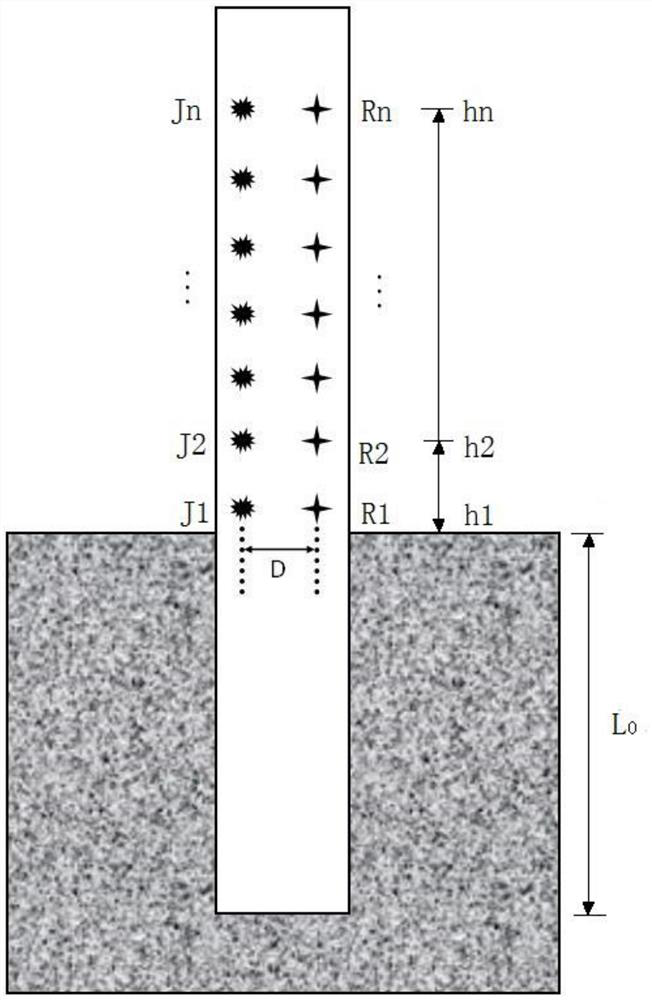
[0028] 1) Measuring point layout: multiple excitation points and multiple receiving points are arranged at intervals at different elevations along the axis of the pile; for example figure 2 As shown, the multiple excitation points are the excitation point J1, the excitation point J2... the excitation point Jn arranged sequentially from bottom to top, wherein n>3; the multiple receiving points are sequentially arranged from bottom to top Uniformly arranged receiving point R1, receiving point R2...receiving point Rn, wherein, n>3; any adjacent two of the excitation point J1, excitation point J2...excitation point Jn are equally spaced or not Arranged at equal intervals; the excitation point J1, the excita...


PUM


Abstract

The invention discloses a pile length detection method based on a zero offset distance method. The method comprises the following steps of arrangement of measuring points, wherein a plurality of excitation points and a plurality of receiving points are arranged in the axial direction of a pile body at intervals; data acquisition, wherein the excitation points at different elevation positions are sequentially knocked to generate excitation signals, and multiple detected waveform signals are synchronously received at the receiving points; receiving distance correction, wherein direct wave take-off scattered points in each waveform signal are picked up one by one and transferred to a zero point; pickup of pile bottom reflected waves, wherein after the receiving distance correction, take-off scattered points of the pile bottom reflected waves in each waveform signal are picked up one by one; straight-line fitting of the pile bottom reflected waves, wherein the take-off scattered points reflected by a pile bottom are subjected to straight-line fitting to obtain a reflected wave straight line equation; calculation of the buried depth of the pile body, wherein the buried depth of the pilebody is calculated according to the reflected wave straight line equation. By means of the detection method, the excitation points and the detection points are synchronously arranged along the pile body at different heights, the take-off time of the pile bottom reflected waves is obtained, the elastic wave velocity and buried depth of the pile body are finally obtained, and the detection precision is high.

Description

technical field [0001] The invention relates to the technical field of pile length detection field, in particular to a pile length detection method based on zero offset method. Background technique [0002] The low strain integrity testing method is based on the one-dimensional wave theory. The pile is assumed to be a one-dimensional elastic continuous rod. The elastic wave is generated by exciting the top of the pile body, and the elastic wave propagates down the pile body. When At the interface where there are obvious differences in the pile body (such as pile bottom, broken pile and severe segregation, etc.) or the section area of ​​the pile body changes (such as shrinkage or expansion), the wave impedance will change and generate reflected waves. The sensor receives the reflected signal, amplifies, filters and processes the received reflected signal, and can identify the reflected information from different parts of the pile body. Using the corresponding relationship be...

Claims


Application Information

Patent Timeline
Patent Type & Authority Patents(China)
IPC IPC(8): E02D33/00G01B17/00
CPCE02D33/00G01B17/00
Inventor 刘铁华张邦刘铁化希瑞卞友艳林昀崔德海肖立锋蔡盛赵威韦德江雷理卿志杨正国刘伟陈洪杰
Owner CHINA RAILWAY SIYUAN SURVEY & DESIGN GRP
Learn More