
Novel practical anchor rod pile

An anchor pile, a practical technology, applied in sheet pile walls, protection devices, buildings, etc., can solve the problems of deformation anchor piles, insufficient self-weight, limited self-weight, etc., and achieve increased stability and great practical value. , easy to use effect

Pending Publication Date: 2019-03-29
JIANGSU XINGSHA CONSTR ENG GRP
View PDF13 Cites 1 Cited by
  • Summary
  • Abstract
  • Description
  • Claims
  • Application Information

AI Technical Summary

Problems solved by technology

[0004] The purpose of the present invention is to provide a new type of practical anchor pile to solve the problem that the self-weight of the structural bottom plate proposed in the above background technology is not enough to resist the buoyancy of groundwater, resulting in damage or deformation and the limited pull-out resistance of the existing anchor pile.

Method used


Image

  • Novel practical anchor rod pile
  • Novel practical anchor rod pile
  • Novel practical anchor rod pile

Examples


Embodiment 1

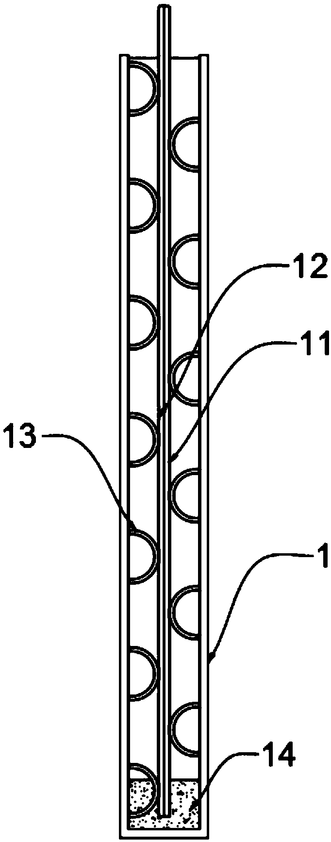
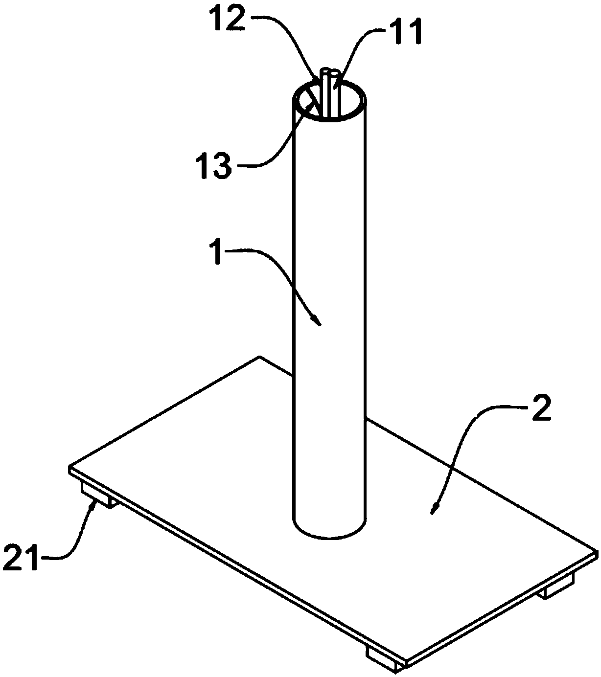
[0029] A new practical anchor pile, such as figure 1 and figure 2 As shown, the anchor pile body 1 is included, and the inside of the anchor pile body 1 is vertically provided with a first steel bar 11, and one side of the first steel bar 11 is provided with a water pipe 12, and the top of the first steel bar 11 and the water pipe 12 Both pass through the top opening of the anchor pile body 1, the anchor pile body 1 is a hollow tubular structure with an opening at the top, and the inner walls on both sides of the anchor pile body 1 are provided with a number of second reinforcement bars 13, the second reinforcement bars 13 It is a semi-circular arc structure, the upper and lower ends of the second steel bar 13 are tightly welded with the inner wall of the anchor pile body 1 respectively, the inner bottom surface of the anchor pile body 1 is provided with a grouting filling area 14, and the bottom of the anchor pile body 1 A bottom plate 2 is provided, and the bottom plate 2 ...

Embodiment 2

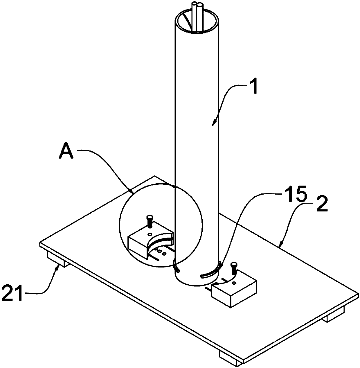
[0036] In specific use, the bottom of the anchor pile body 1 is easily subject to the buoyancy of groundwater when it is fixed and moves upward in the morning. Therefore, we make improvements to the anchor pile body 1 on the basis of Embodiment 1, as image 3 and Figure 4 As shown, the outer walls on both sides of the bottom of the anchor pile body 1 are symmetrically and tightly welded with clamping strips 15, and the outside of the clamping strips 15 is provided with a movable block 3, and the side of the movable block 3 close to the anchor pile body 1 is provided with a concave Groove 31 , the inside of the groove 31 is provided with a clamping groove 311 , and the clamping groove 311 is engaged with the clamping bar 15 by clamping.

[0037] Further, the top of the bottom plate 2 is provided with two chute 22 near the movable block 3, and the bottom of the movable block 3 is provided with a slider 34 near the chute 22, and the slider 34 is slidably connected with the chute...


PUM


Abstract

The invention relates to the technical field of anchor rod piles, in particular to a novel practical anchor rod pile which comprises an anchor rod pile body. A first reinforcing rod is vertically arranged in the anchor rod pile body. A water pipe is arranged on one side of the first reinforcing rod. The anchor rod pile body is of a hollow tubular structure with an opening in the top end. The innerwalls of the two sides of the anchor rod pile body are each provided with a plurality of second reinforcing rods. Each second reinforcing rod is of a semi-arc-shaped structure. The upper end and thelower end of each second reinforcing rod are closely welded to the inner wall of the anchor rod pile body. The inner bottom face of the anchor rod pile body is provided with a grouting filling area. Abottom plate is arranged at the bottom of the anchor rod pile body. The anchor rod pile can prevent floor sinking, inclining and the like and has the effects of pulling resistance, pressure resistance, shear resistance and the like, no reinforcement cage needs to be bound, cost can be saved compared with a traditional anchor rod pile by means cement mortar grouting, it can be ensured that the anchor rod pile has quite high pulling resistance by means of a movable block and a clamping strip, and the building stability is greatly increased.

Description

technical field [0001] The invention relates to the technical field of anchor piles, in particular to a novel and practical anchor pile. Background technique [0002] With the rapid development of the national economy and science and technology, urban construction has been implemented on a large scale. In order to better solve the increasingly tense situation of construction land and fully develop and utilize underground space, underground garages and buildings buried underground are gradually increasing, high-rise and super high-rise buildings emerge, and foundations are buried deeper and deeper. At the same time, the development and utilization of basement parts, podiums or relatively independent underground structures as garages and other functions are becoming more and more extensive. [0003] This type of underground structure has a large building area and a deep foundation. Anchor piles are often used during construction. Anchor piles refer to the use of the reaction ...

Claims


Application Information

Patent Timeline
Patent Type & Authority Applications(China)
IPC IPC(8): E02D5/54E02D31/12E02D31/08E02D15/04
CPCE02D5/54E02D15/04E02D31/08E02D31/12E02D2250/003E02D2600/20
Inventor 赵卫政王长乐王士华
Owner JIANGSU XINGSHA CONSTR ENG GRP
Learn More