A giant I-beam straightening system
An I-beam, giant technology, applied in the field of giant I-beam correction system, can solve the problems of long time-consuming correction, single function, narrow use range, etc., to achieve the effect of wide use range, reduce waste and improve service life
- Summary
- Abstract
- Description
- Claims
- Application Information
AI Technical Summary
Problems solved by technology
Method used
Image

Examples
Embodiment approach
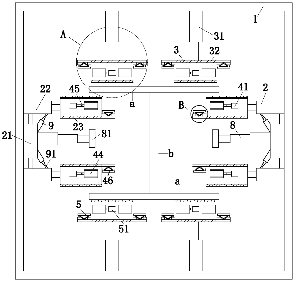
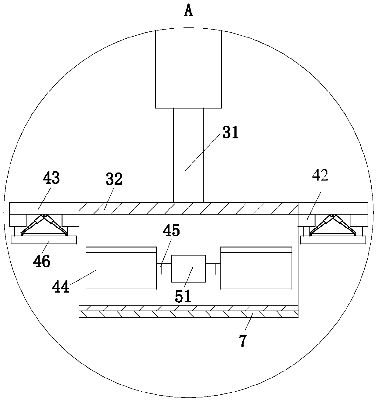
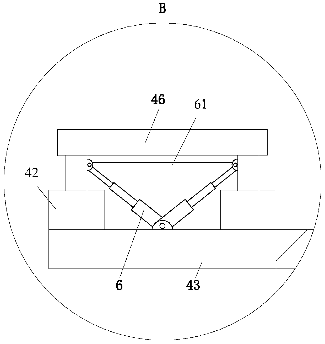
[0024]As a specific embodiment of the present invention, the No. 1 correction plate 23 and the No. 2 correction plate 32 are both hollow structures, and the No. 1 correction auxiliary unit 4 and the No. 2 correction auxiliary unit 4 and the No. The No. 1 correction auxiliary unit 5, the No. 1 correction auxiliary unit 4 is used to increase the length of the No. 1 correction plate 23 to adapt to the giant I-beams of different bending degrees, and the No. 2 correction auxiliary unit 5 is used to increase the length of the No. 2 correction plate 32. The length is to adapt to the giant I-beam of different bending degrees; the No. 1 correction auxiliary unit 4 includes the No. 2 cylinder 41, the No. 3 cylinder 42 and the support seat 43, and the No. 2 cylinder 41 is located inside the No. 1 correction plate 23, and its input end and the side wall of the No. 1 correction plate 23 are affixed, and the output end of the No. 2 cylinder 41 is provided with the No. 3 correction plate 44, ...
Embodiment 2
[0030] Embodiment 2: When the bending degree of the giant I-beam needs to be corrected is too large, and the length of the No. 1 correction plate 23 and the No. 2 correction plate 32 is smaller than the bending degree of the giant I-beam, the No. 1 correction auxiliary unit 4 and the No. 2 correction The correction auxiliary unit 5 starts to work. When the No. 1 correction auxiliary unit 4 works, the controller controls the No. 2 cylinder 41 to work. When the No. 2 cylinder 41 works, the No. 3 correction plate 44 is pushed out from the No. 1 correction plate 23. When the stretching length of the correction plate 44 is the same as the length of the No. 2 electromagnet 46, the controller controls the No. 1 electromagnet to power off, the No. 2 electromagnet 46 is energized, and after the No. 2 electromagnet 46 absorbs and fixes the No. 3 correction plate 44, The controller controls the No. 3 cylinder 42 to work, and the output end of the No. 3 cylinder 42 drives the No. 3 correct...
Embodiment 3
[0031] Embodiment 3: When the web part of the giant I-beam needs to be corrected, repeat the steps of fixing the giant I-beam in Embodiment 1. After the giant I-beam is fixed, the controller controls the electric telescopic rod 8 to work, and the electric telescopic rod 8 Push the No. 4 correction plate 81 to move towards the web of the giant I-beam during work, and the adjacent No. 4 correction plate 81 can correct the web of the giant I-beam when it moves in the opposite direction.
PUM
 Abstract
Description
Claims
Application Information
 - R&D
- Intellectual Property
- Life Sciences
- Materials
- Tech Scout
- Unparalleled Data Quality
- Higher Quality Content
- 60% Fewer Hallucinations
Browse by: Latest US Patents, China's latest patents, Technical Efficacy Thesaurus, Application Domain, Technology Topic, Popular Technical Reports.
© 2025 PatSnap. All rights reserved.Legal|Privacy policy|Modern Slavery Act Transparency Statement|Sitemap|About US| Contact US: help@patsnap.com