
Patsnap Eureka
For R&D, Patsnap Eureka makes reading and utilizing patents & technical documents easy.
Patsnap Eureka AIR
Designed for self-driven R&D workflows. Generate viable solutions, solve complex R&D challenges, empower your innovation with AI.

Patsnap Eureka Materials
Designed for material experts only. Revolutionize your material R&D, from search, analyze, to developing new materials.

TechResearch
Generate reliable direction feasibility study reports for your R&D in just a few steps.

TechSeek
Discover and master advanced knowledge NOW. Basics, ideas, possibilities, all at once.

TechMind
As an expert in R&D Theories, TechMind can generates customized viable solutions instantly.

TechRisk
Analyze your overall solution with one click, know your potential R&D risks in advance.

TechMonitor
Get weekly tech updates, stay abreast of the latest tech innovations and key insights.
Pneumatic suction head for baked biscuits
A technology of biscuits and suction cups, applied in baking, food ovens, food science, etc., can solve problems such as inability to filter, blockage of the start-up system, etc., and achieve the effects of preventing system blockage, increasing the suction area, and smoothing the suction process
- Summary
- Abstract
- Description
- Claims
- Application Information
AI Technical Summary
Problems solved by technology
Method used
Image

Examples
Embodiment 1
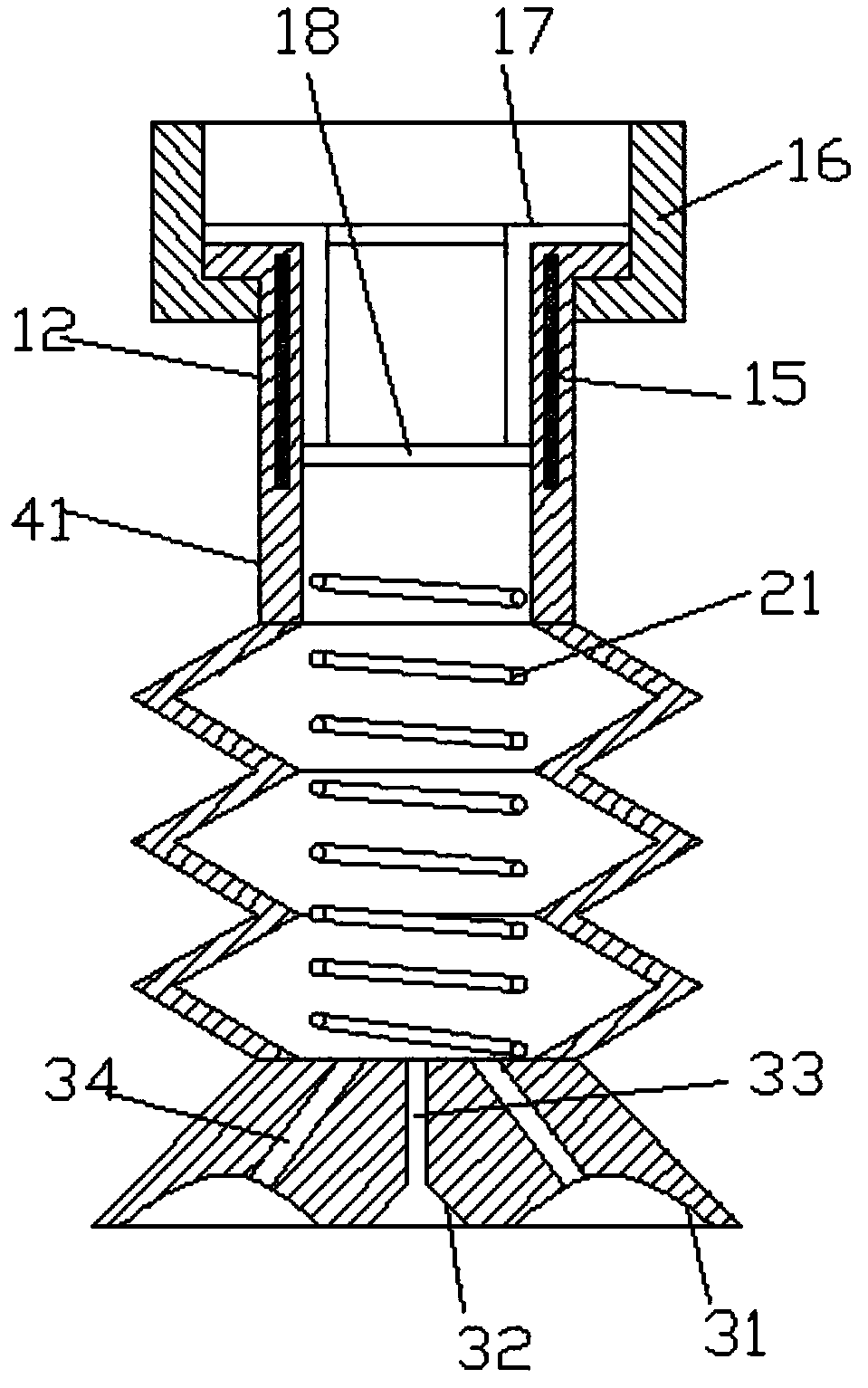
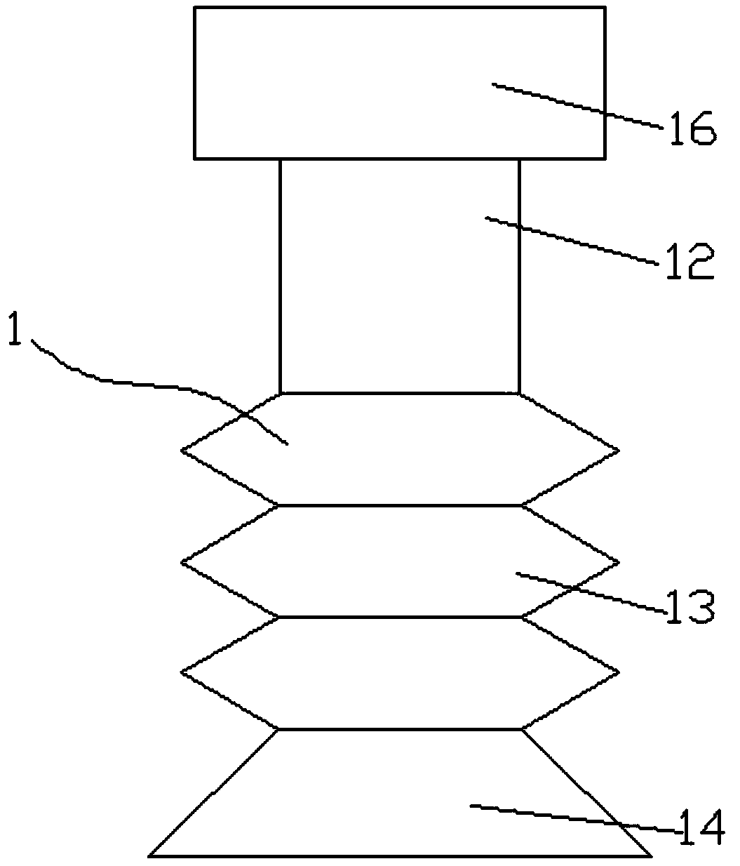
[0018] combine figure 1 , figure 2 As shown; a pneumatic suction head for baking biscuits, including a suction head body 1, the suction head body 1 includes a tailstock 12, a buffer section 13, and a suction head section 14, and an annular support plate 15 is embedded inside the tailstock 12, The outer ring of the tailstock 12 is installed with a fixed nut 16, and the end of the tailstock 12 is installed with a support frame 17. The end of the support frame 17 is located inside the sleeve where the tailstock 12 is installed, and a filter screen is installed at the end of the support frame 17. plate 18. When the suction head sucks the biscuit, the filter plate at the end of the support frame is used to filter the inhaled gas to prevent the residue on the surface of the biscuit from entering the interior of the pneumatic system and prevent the system from being blocked
[0019] A steel mesh structure is embedded inside the buffer section 13 , and a buffer spring 21 is install...
Embodiment 2
[0023] combine figure 1 , figure 2 As shown; a pneumatic suction head for baking biscuits, including a suction head body 1, the suction head body 1 includes a tailstock 12, a buffer section 13, and a suction head section 14, and an annular support plate 15 is embedded inside the tailstock 12, The outer ring of the tailstock 12 is installed with a fixed nut 16, and the end of the tailstock 12 is installed with a support frame 17. The end of the support frame 17 is located inside the sleeve where the tailstock 12 is installed, and a filter screen is installed at the end of the support frame 17. plate 18. When the suction head sucks the biscuit, the filter plate at the end of the support frame is used to filter the inhaled gas to prevent the residue on the surface of the biscuit from entering the interior of the pneumatic system and prevent the system from being blocked
[0024] A steel mesh structure is embedded inside the buffer section 13 , and a buffer spring 21 is install...
PUM
 Abstract
Description
Claims
Application Information
 - R&D Engineer
- R&D Manager
- IP Professional
- Industry Leading Data Capabilities
- Powerful AI technology
- Patent DNA Extraction
Browse by: Latest US Patents, China's latest patents, Technical Efficacy Thesaurus, Application Domain, Technology Topic, Popular Technical Reports.
© 2024 PatSnap. All rights reserved.Legal|Privacy policy|Modern Slavery Act Transparency Statement|Sitemap|About US| Contact US: help@patsnap.com